Brake control device

a technology of brake control and control device, which is applied in the direction of brake system, brake components, transportation and packaging, etc., can solve the problems of cumbersome bolt removal, reduced device size, and complicated assembly operation

Active Publication Date: 2013-05-30
MITSUBISHI HEAVY IND ENG LTD
View PDF1 Cites 4 Cited by
  • Summary
  • Abstract
  • Description
  • Claims
  • Application Information

AI Technical Summary

Benefits of technology

[0015]In the above-mentioned brake control device, the variable load valve which requires maintenance, is fitted to the main unit so as to be accessible and removabl

Problems solved by technology

Typically, because the space for mounting the brake control device on the vehicle is small, there is a problem in how to reduce the size of the device while still maintaining its performance.
Therefore, there is the problem in that the assembly operation is complicated, furthermore, removal of the bolts is

Method used


Image

  • Brake control device
  • Brake control device
  • Brake control device

Examples


Embodiment Construction

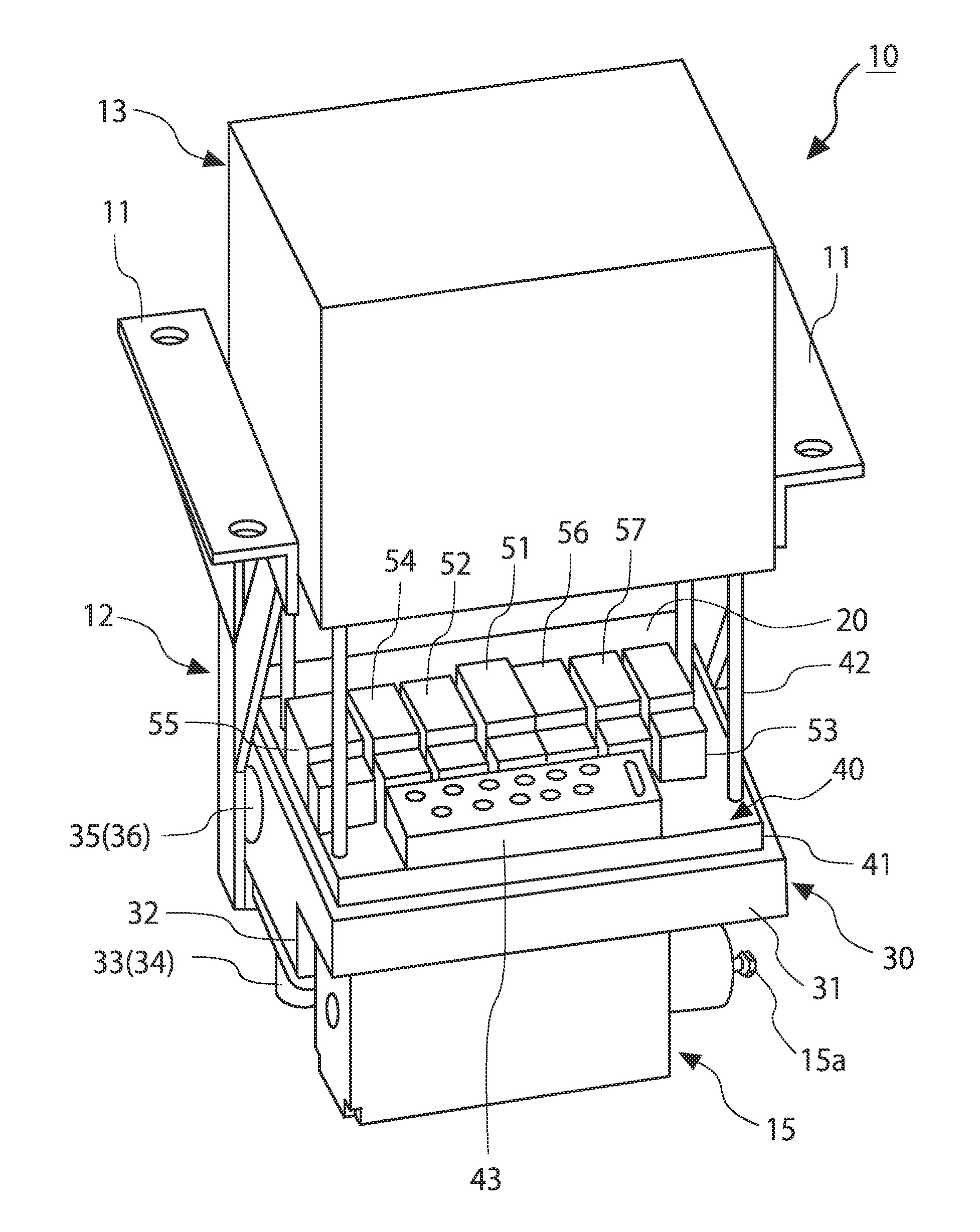
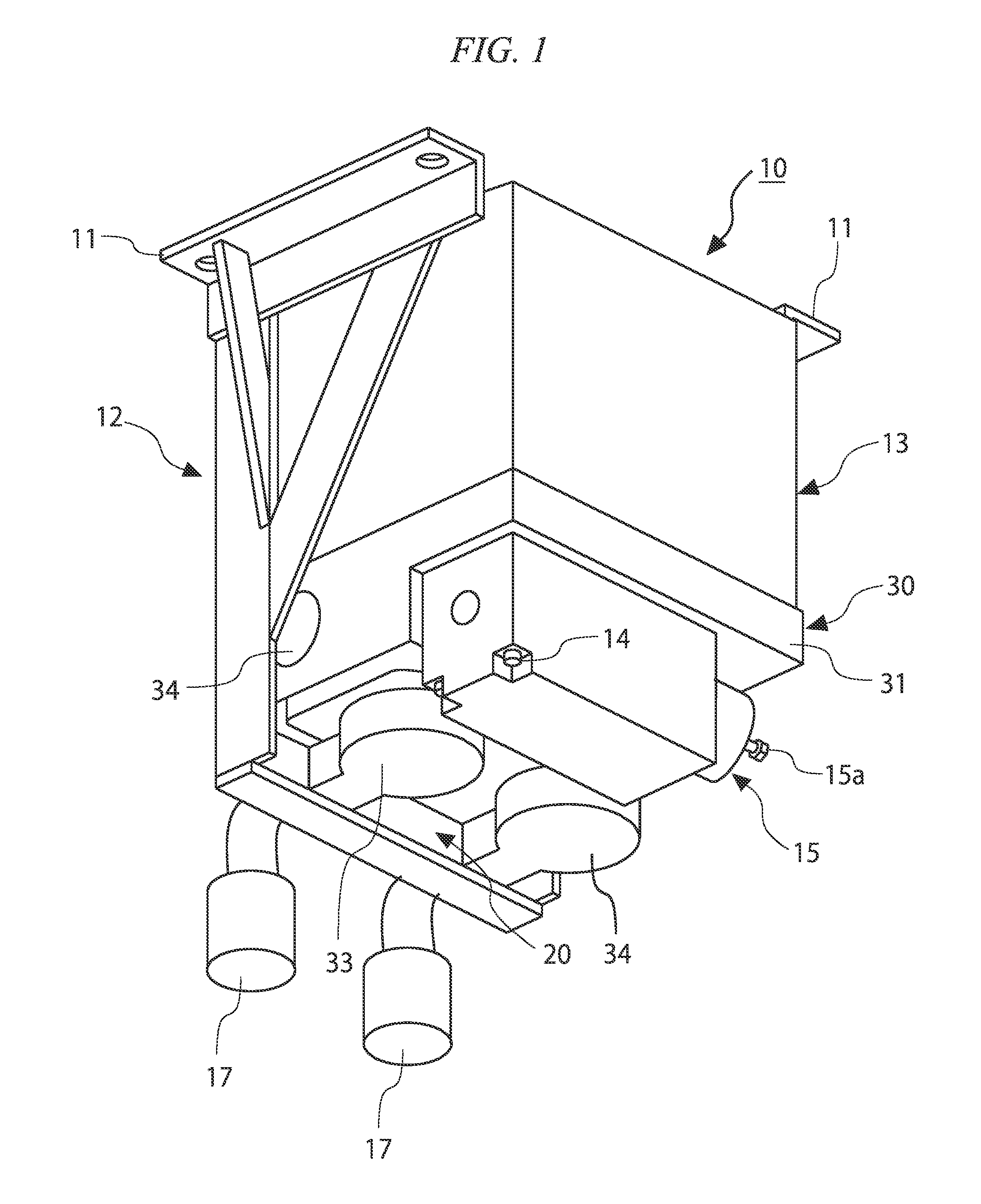
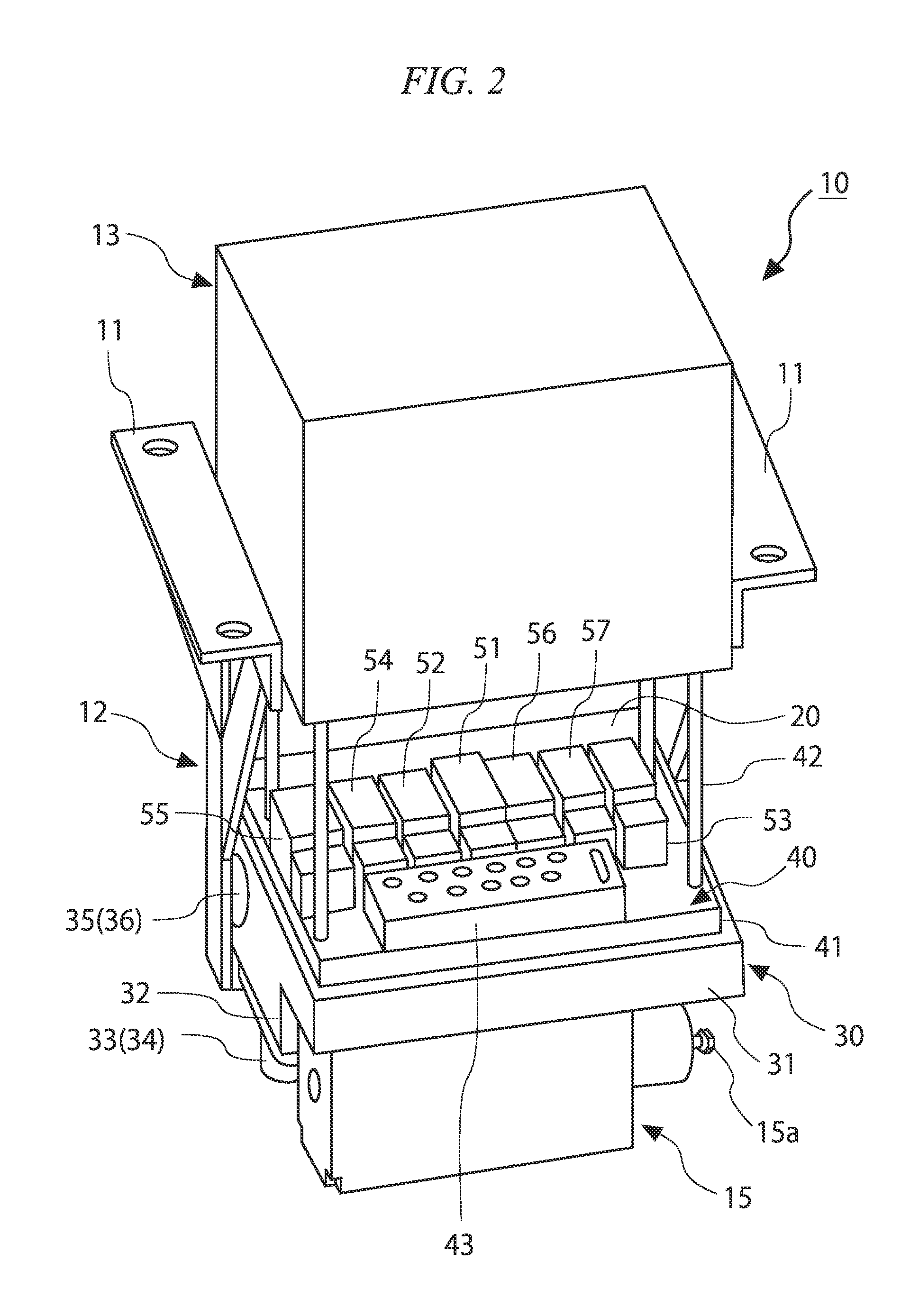
[0023]Next, a brake control device according to an embodiment of the present invention is described with reference to the drawings. The embodiment described below is a preferred specific example of the brake control device of the present invention, and is subject to various restrictions considered technically favorable. However, the technical scope of the invention is not limited thereto unless specifically stated. Furthermore, the constituent elements of the embodiment described below can be replaced and substituted as needed by existing constituent elements or the like, and a number of variations are possible including combinations with other existing constituent elements. Accordingly, the descriptions of the embodiment below are not to be construed as limiting the contents of the invention as described in the claims.

[0024]The brake control device according to one embodiment of the present invention is a control device for a brake device for braking (specifically air braking) a ra...


PUM


Abstract

A brake control device includes: a relay valve that generates a first drive pressure for driving a brake, from an air pressure generated by a first air supply source, based on an pilot pressure applied; a double check valve that connects the relay valve and a second air supply source that generates a second drive pressure separate to the first air supply source, and that communicates the drive pressure which is generated in either the relay valve or the second air supply source, with the brake; a variable load valve that outputs a first pressure according to a pressure of an air spring fitted on a vehicle side; a first solenoid valve group which generates the pilot pressure from the air pressure during service operation; and a second solenoid valve group which outputs, as the pilot pressure, a second pressure according to the first pressure output from the variable load valve during emergency operation.

Description

TECHNICAL FIELD[0001]The present invention relates to a brake control device which is installed in a railway vehicle and operates an air brake.[0002]Priority is claimed on Japanese Patent Application No. 2011-262823, filed Nov. 30, 2011, the contents of which are incorporated herein by reference.BACKGROUND ART[0003]Conventionally, there is known a brake control device for a railway vehicle, comprising as a brake system for service operation; a pressure control section which outputs a brake command signal (electric signal), a solenoid valve which outputs a brake command pressure (air pressure) according to the brake command signal, and a relay valve which, using the brake command pressure output by the solenoid valve as a control pressure, applies amplification accordingly and outputs the resulting air pressure to a brake cylinder. As a brake system for emergency operation, the brake control device comprises a variable load valve which detects pressure variation in proportion to the ...

Claims


Application Information

Patent Timeline
IPC IPC(8): B60T13/40
CPCB60T13/40B60T13/662B60T13/683B60T8/3675Y10S303/10B60T17/228B60T8/1893B60T15/027B60T15/18B60T15/36B60T8/30
Inventor KOMORIYA, TOSHIHIKOYAMASHITA, TERUO
Owner MITSUBISHI HEAVY IND ENG LTD
Why Eureka
Try Eureka