Hydraulic control apparatus for a multi-stage automatic transmission

a technology of automatic transmission and hydraulic control apparatus, which is applied in the direction of gearing control, gearing elements, gearing, etc., can solve the problems of downshifting of two or more stages, restarting the vehicle, etc., and achieves low speed, high speed, and low speed. , the effect of a relatively high speed

Active Publication Date: 2007-07-12
AISIN AW CO LTD +1
View PDF6 Cites 18 Cited by
  • Summary
  • Abstract
  • Description
  • Claims
  • Application Information

AI Technical Summary

Benefits of technology

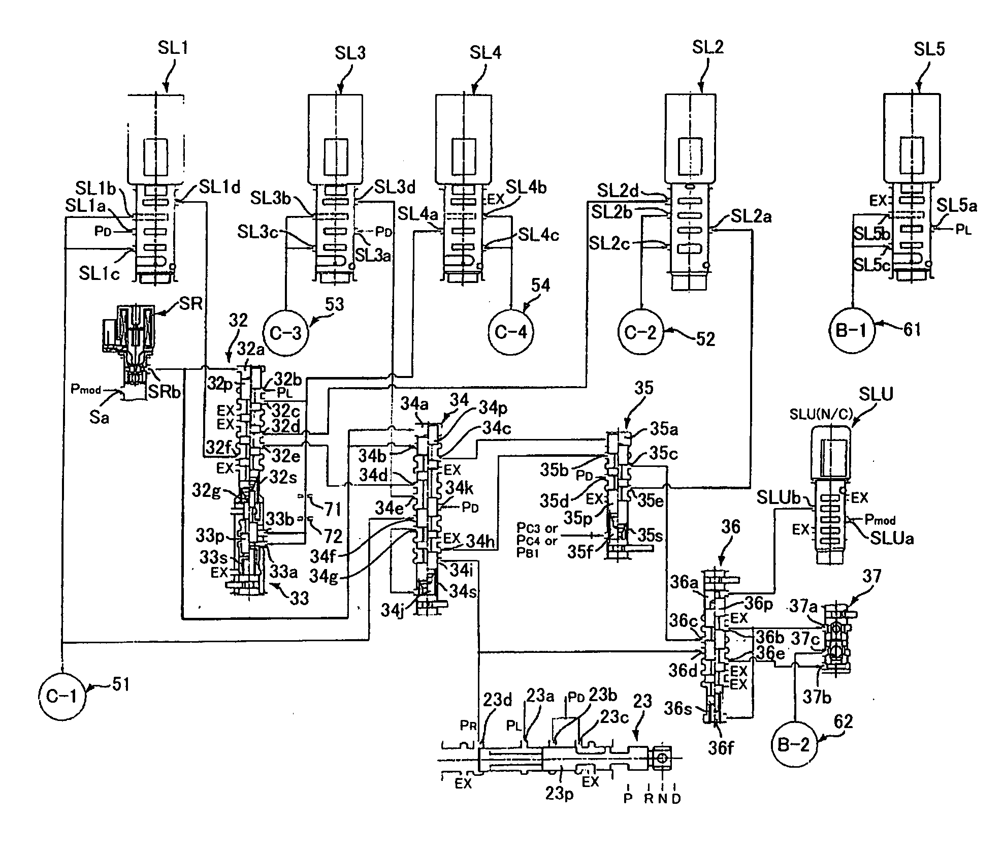
[0010] According to the first aspect of the invention, during a failure in which all of the solenoid valves are de-energized, the first switching valve outputs a forward range pressure as a reverse input pressure, the second switching valve, which is locked at the second position due to the lock pressure, supplies an engagement pressure to the second hydraulic servo by inputting the reverse input pressure to the discharge port of the second engagement pressure control solenoid valve, and the second switching valve, which is set at the first position by interrupting the lock pressure after restarting the engine, supplies an engagement pressure to the first hydraulic servo by inputting a reverse input pressure to the discharge port of the first engagement pressure control solenoid valve. Therefore, while the vehicle is traveling, it is possible to lock the shift speed at a relatively high speed. In addition, while the downshifting of two or more speeds can be prevented, by restarting the engine, for example, after temporarily stopping the vehicle, it is possible to set the shift speed at a relatively low speed, and it is possible to enable restarting of the vehicle.
[0011] According to the second aspect of the invention, because the second switching valve feeds line pressure to serve as lock pressure when at the second position, during the normal engine start-up, it is possible to lock the shift speed at the second position based on the line pressure. Thus, while the vehicle is traveling, it is possible to lock the shift speed at a relatively high speed even during a failure in which all of the solenoid valves are de-energized. In addition, by stopping the engine, the locking of the second switching valve is released based on the line pressure and the second switching valve can be set at the first position that interrupts the line pressure. Thus, by restarting the engine, it is possible to set the shift speed at a relatively low speed and it is possible to enable restarting of the vehicle.
[0012] According to the third aspect of the invention, a fail solenoid valve is provided that outputs a signal pressure during a de-energized state and interrupts the signal pressure after reverting to the energized state at least during a normal engine start-up. The second switching valve inputs the signal pressure of the fail solenoid valve before being locked by the lock pressure during a failure in which all of the solenoid valves are de-energized and is switched to the first position due to this signal pressure. Therefore, by restarting the engine, it is possible to set the shift speed at a relatively low speed.
[0016] According to the seventh aspect of the invention, the second spool of the second switching valve is set to the second position by abutting the second spool to the third spool when the third spool of the third switching valve is at the urging position. Therefore, even when, for example, a state occurs in which the third spool of the third switching valve sticks and the lock pressure is not communicated to the second switching valve, it is possible to maintain the second spool at the second position due to the abutment of the third spool. Thereby, even when, for example, the third spool sticks, it is possible to prevent the second spool from being set at the first position, at which an engagement pressure is supplied to the first hydraulic server. In addition, even during a failure in which all of the solenoid valves are de-energized while the vehicle is traveling, it is possible to reliably lock the shift speed at a relatively high speed and it is possible to reliably prevent the downshifting of two or more speeds from occurring.
[0018] According to the ninth aspect of the invention, the first switching valve outputs a reverse input pressure directly to a discharge port of the third engagement pressure control solenoid valve during a failure in which all of the solenoid valves are de-energized and supplies an engagement pressure to the third hydraulic servo that engages and disengages the friction engagement elements that engage at a relatively low speed and a relatively high speed. Therefore, it is possible to enable establishing a relatively low speed and a relatively high speed.
[0019] According to the tenth aspect of the invention, the fourth engagement pressure control solenoid valve inputs a lock pressure to an input port via the second switching valve as a line pressure. Therefore, before all of the solenoid valves become de-energized, it is possible to determine whether or not the first switching valve feeds the lock pressure normally depending on whether or not the shift speed that is established normally by the friction engagement element engaged by the fourth hydraulic servo has been attained. Thereby, for example, in the case in which the first switching valve is not locked by the lock pressure, all of the solenoids are set to be de-energized, and it is possible to prevent the occurrence of unintended downshifting and thereby ensure safe travel of the vehicle.

Problems solved by technology

However, in such a hydraulic control apparatus described above, a state in which electrical signals from the solenoid valves are not sent, which is referred to as a all-solenoids-off fail state, may occur when, for example, there is a severed wire or short, or when, for example, some type of failure is detected in the hydraulic control apparatus.
In such a multi-stage automatic transmission, during the all-solenoids-off fail while traveling as described above, there is a concern that downshifting of two or more stages (for example, from fifth to third speed) may occur due to separating and locking the shift speed at two predetermined stages (relatively high and low speeds), and downshifting of two or more steps occurring when this is not intended or preferred by the driver.
However, simply locking at the high speed makes restarting the vehicle after temporarily stopping the vehicle difficult, and there is a concern that a vehicle that is experiencing failure will not be capable of self-propulsion if it is simply locked at a high speed.

Method used


Image

  • Hydraulic control apparatus for a multi-stage automatic transmission
  • Hydraulic control apparatus for a multi-stage automatic transmission
  • Hydraulic control apparatus for a multi-stage automatic transmission

Examples


Embodiment Construction

[0029] Below, exemplary embodiments of the present invention will be explained with reference to FIG. 1 through FIG. 8A to FIG. 8C.

Configuration of Automatic Transmission

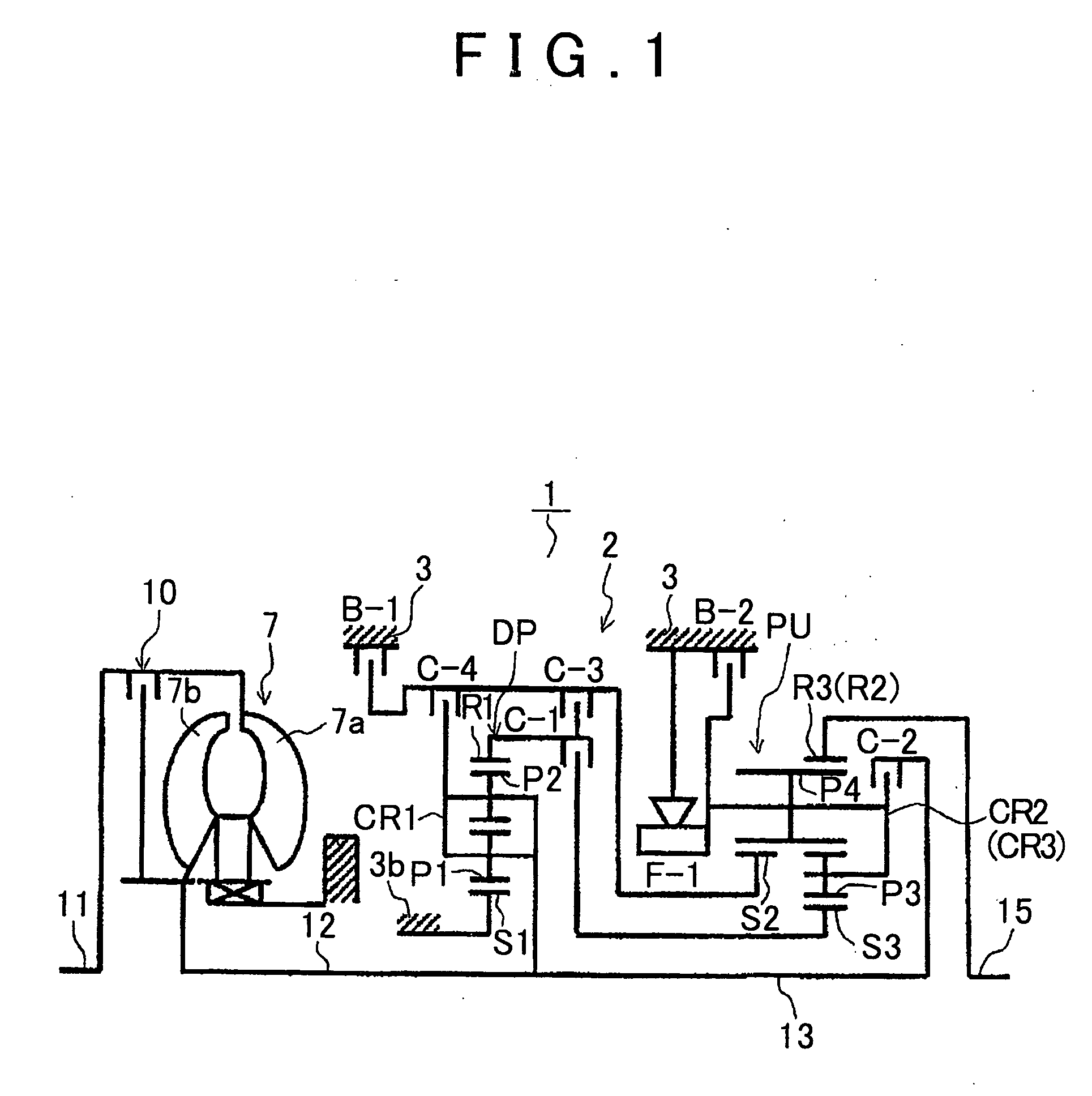
[0030] First, a schematic structure of the multi-stage automatic transmission (below, referred to simply as an “automatic transmission”) in which an exemplary embodiment of the present invention can be applied will be explained with reference to FIG. 1. As shown in FIG. 1, a preferable automatic transmission 1 that is used, for example, in an FR type (front engine, rear drive) vehicle has an input shaft 11 for the automatic transmission 1 that is able to connect to an engine (not illustrated), and is provided with a torque converter 7 that is disposed concentrically with the input shaft 11 in the axial direction and a speed change mechanism 2.

[0031] The torque converter 7 has a pump impeller 7a that is connected to the input shaft 11 of the automatic transmission 1 and a turbine runner 7b to which the rotation o...


PUM


Abstract

A hydraulic control apparatus for a multi-stage automatic transmission includes solenoid valves such as the linear solenoid valves that are formed as normally closed valves. A first clutch apply relay valves that outputs a forward range pressure as a reverse input pressure during an all-solenoid-off mode, and a second clutch apply relay valves that switches between a left half position that inputs a reverse input pressure to a discharge port and a right half position that inputs the reverse pressure to the discharge port are provided. The second clutch apply relay valve is set to the right half position during normal engine startup and locked based on the lock pressure by feeding the line pressure as a lock pressure and is set at the left half position that interrupts the lock pressure after the engine is restarted during all-solenoids-off.

Description

INCORPORATION BY REFERENCE [0001] This application claims priority from Japanese Patent Application Nos. 2005-378389, 2005-378390, and 2005-378391, all filed on Dec. 28, 2005, the disclosures of which, including the specifications, drawings and abstracts, are incorporated herein by reference in their entirety. BACKGROUND OF THE INVENTION [0002] 1. Field of the Invention [0003] The present invention relates to a hydraulic control apparatus for a multi-stage automatic transmission that is mounted, for example, in a vehicle, and in particular, relates to a hydraulic control apparatus for a multi-stage automatic transmission that ensures the ability of the vehicle to travel during an all-solenoids-off failure. [0004] 2. Description of the Related Art [0005] Conventionally, a staged automatic transmission that is mounted, for example, on a vehicle enables multi-speed shifting by controlling the engagement state of a plurality of friction engagement elements (clutches and brakes) by using...

Claims


Application Information

Patent Timeline
Patent Type & Authority Applications(United States)
IPC IPC(8): F16H31/00F16H61/12
CPCF16H61/12F16H2061/122F16H2061/1232F16H2061/126Y10S477/906Y10T477/6939Y10T477/693973Y10T477/6936Y10T477/693635
Inventor HAYASHI, TAKAYUKIYAMAGUCHI, TETSUYANODA, KAZUYUKITODO, MINORUOZAKI, KAZUHISANOZAKI, KAZUTOSHIHONDA, ATSUSHI
Owner AISIN AW CO LTD
Why Eureka
Try Eureka