Electro-pneumatic brake

A technology of electro-pneumatic braking and braking machine, applied in the direction of brakes, braking components, railway braking systems, etc., can solve problems such as non-compliance with standard requirements

Active Publication Date: 2019-01-25
QINGDAO SRI TECH CO LTD
View PDF8 Cites 18 Cited by
  • Summary
  • Abstract
  • Description
  • Claims
  • Application Information

AI Technical Summary

Problems solved by technology

[0005] At present, domestic electro-pneumatic brakes are designed based on China Nat

Method used


Image

  • Electro-pneumatic brake
  • Electro-pneumatic brake
  • Electro-pneumatic brake

Examples


Embodiment Construction

[0056] The invention discloses an electric-pneumatic brake to meet the UIC540-2006 standard.

[0057] The following will clearly and completely describe the technical solutions in the embodiments of the present invention with reference to the accompanying drawings in the embodiments of the present invention. Obviously, the described embodiments are only some, not all, embodiments of the present invention. Based on the embodiments of the present invention, all other embodiments obtained by persons of ordinary skill in the art without making creative efforts belong to the protection scope of the present invention.

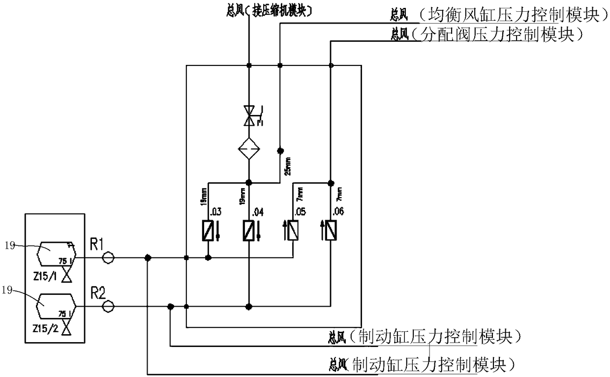
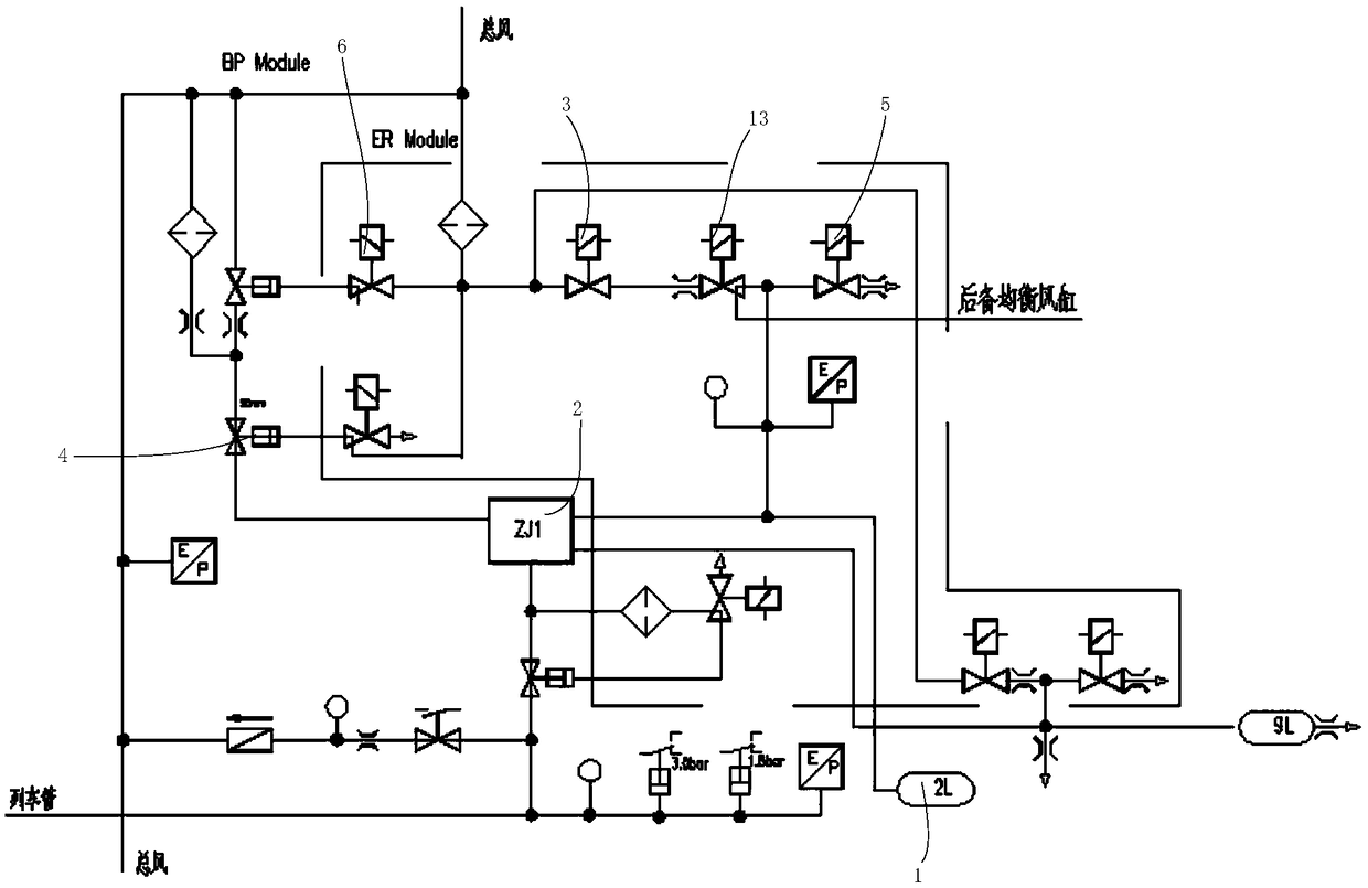
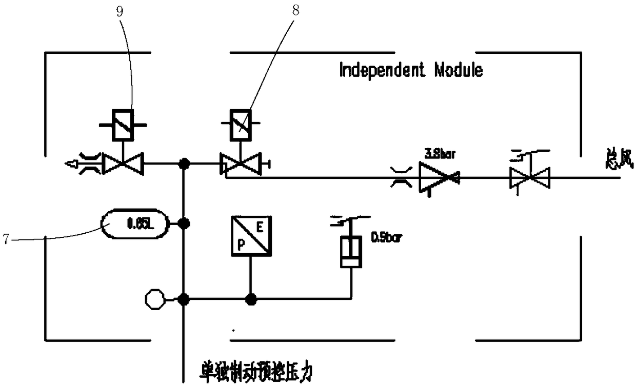
[0058] see Figure 1-Figure 10 , figure 1 Schematic diagram of the structure of the general wind module provided by the embodiment of the present invention; figure 2 Schematic diagram of the structure of the balanced air cylinder pressure control module provided by the embodiment of the present invention; image 3 Schematic diagram of the structure of the individ...


PUM


Abstract

The invention discloses an electro-pneumatic brake, comprising a main air module, a balanced air cylinder pressure control module, a brake pressure regulating module and a parking brake pressure control module. The equalizing air cylinder pressure control module is provided with an equalizing air cylinder, a first air supply pipeline for supplying air to the equalizing air cylinder is communicatedwith the main air module, a second air supply pipeline for supplying air to the train pipe and a relay valve are communicated with the main air module, and the relay valve controls the air supply andexhaust of the train pipe through the pressure difference between the equalizing air cylinder and the train pipe. The balanced air cylinder pressure control module controls the gradual pressure change of the train pipe or the pressure stage change of the train pipe, thereby realizing the stage adjustment of the locomotive braking force, in accordance with the UIC 540- 2006 Standard Requirements.

Description

technical field [0001] The invention relates to the technical field of locomotives, in particular to an electropneumatic brake. Background technique [0002] For a long time, AAR (Association of North American Railways) and UIC (International Union of Railways) have defined their respective systems as standards, referred to as AAR system and UIC system. At present, the railways in the United States, Canada and Japan use the AAR system, and Western Europe and former European colonies mostly use the UIC system. Due to historical reasons, the railway rolling stock in my country basically uses the AAR system. [0003] The AAR air automatic braking system is mainly a one-off relief type (also called direct relief type) braking system, that is, in the state of train braking, the pressure of the brake pipe is increased to a certain level, which can realize the complete release of the train brake, and the whole The consistency of train relief is good, and it is suitable for long tr...

Claims


Application Information

Patent Timeline
IPC IPC(8): B61H11/14
CPCB61H11/14B60T13/665B60T13/683B60T17/228
Inventor 方长征周士华刘泉张石峰胡斌
Owner QINGDAO SRI TECH CO LTD
Why Eureka
Try Eureka