Hydraulic control system for use in a motor vehicle and method for controlling the hydraulic control system

a control system and motor vehicle technology, applied in the direction of rotary clutches, fluid couplings, gearings, etc., can solve the problems of inability to detect the switching difficult to reliably distinguish between a non-funcitonal solenoid valve and a relay valve affected by the malfunction of the relay valv

Inactive Publication Date: 2008-05-15
TOYOTA JIDOSHA KK
View PDF0 Cites 17 Cited by
  • Summary
  • Abstract
  • Description
  • Claims
  • Application Information

AI Technical Summary

Benefits of technology

[0010]In accordance with the aspect of the invention, if a switching malfunction occurs that causes the relay valve to be stuck in one position, in which the first destination part becomes the destination of output fluid pressure of the solenoid valve, or the other position, in which the second destination part becomes the destination of output fluid pressure of the solenoid valve, the fluid pressure switch shows an operating state different than that available when a command to switch the relay valve from one position to the other position is given. Furthermore, because a normally produced fluid pressure continues to be supplied to the input port of the relay valve, it is possible to detect the switching malfunction at all times and in a reliable manner.

Problems solved by technology

In this case, however, a failure of an electromagnetic valve that controls switching operation of the relay valve or a failure of the relay valve per se, may result in a switching malfunction in which the relay valve becomes stuck to a flow path through which the control fluid pressure is supplied to the lock-up mechanism to control the torque capacity thereof.
With this detection method, however, it is impossible to detect the switching malfunction of the relay valve if no fluid pressure is produced from the solenoid valve.
In the event of failure of the solenoid valve per se, it is difficult to reliably distinguish between a non-funcitonal solenoid valve or a relay valve affected by the switching malfunction.

Method used


Image

  • Hydraulic control system for use in a motor vehicle and method for controlling the hydraulic control system
  • Hydraulic control system for use in a motor vehicle and method for controlling the hydraulic control system
  • Hydraulic control system for use in a motor vehicle and method for controlling the hydraulic control system

Examples


Embodiment Construction

[0023]Hereinafter, an embodiment of the present invention will be described in detail with reference to the accompanying drawings.

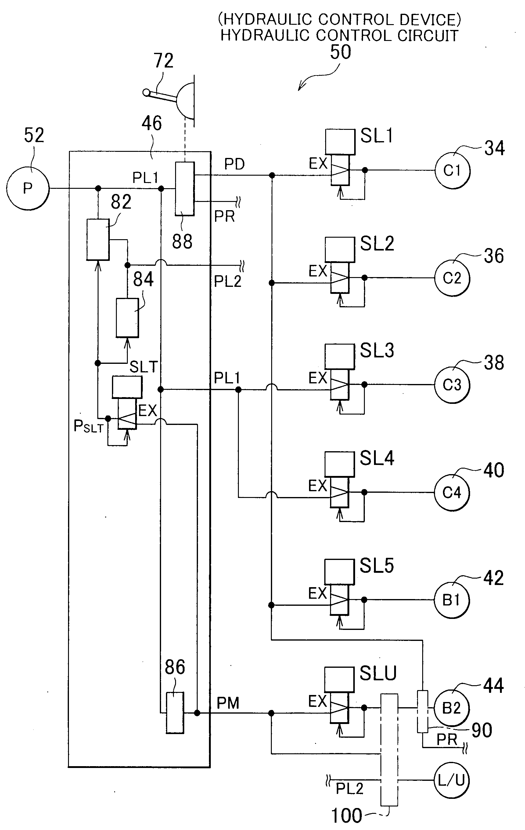
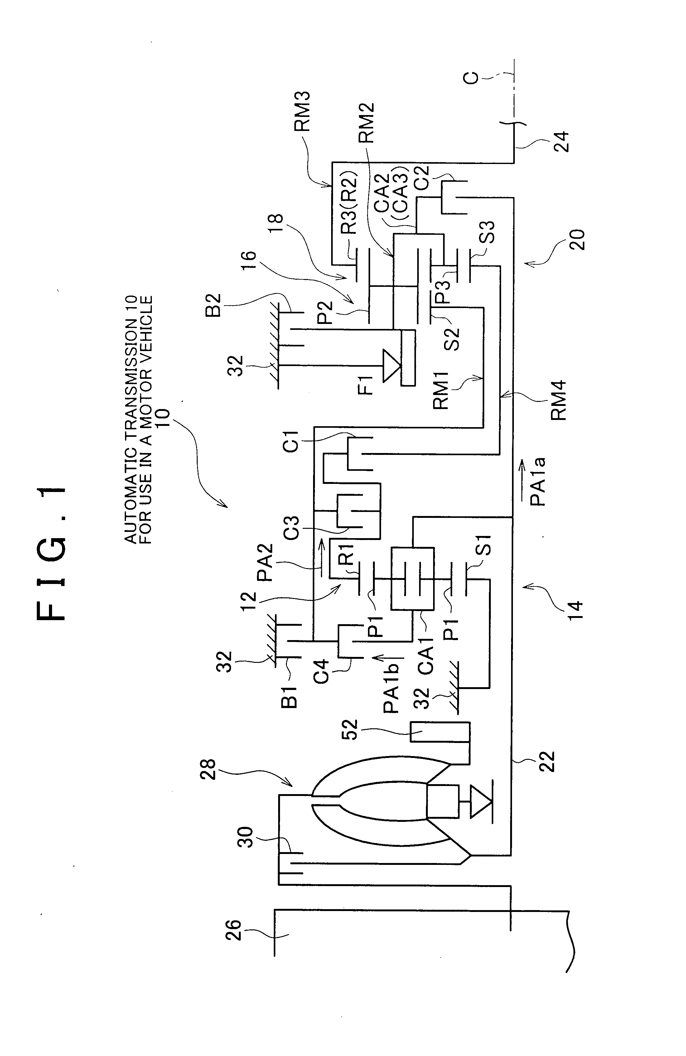
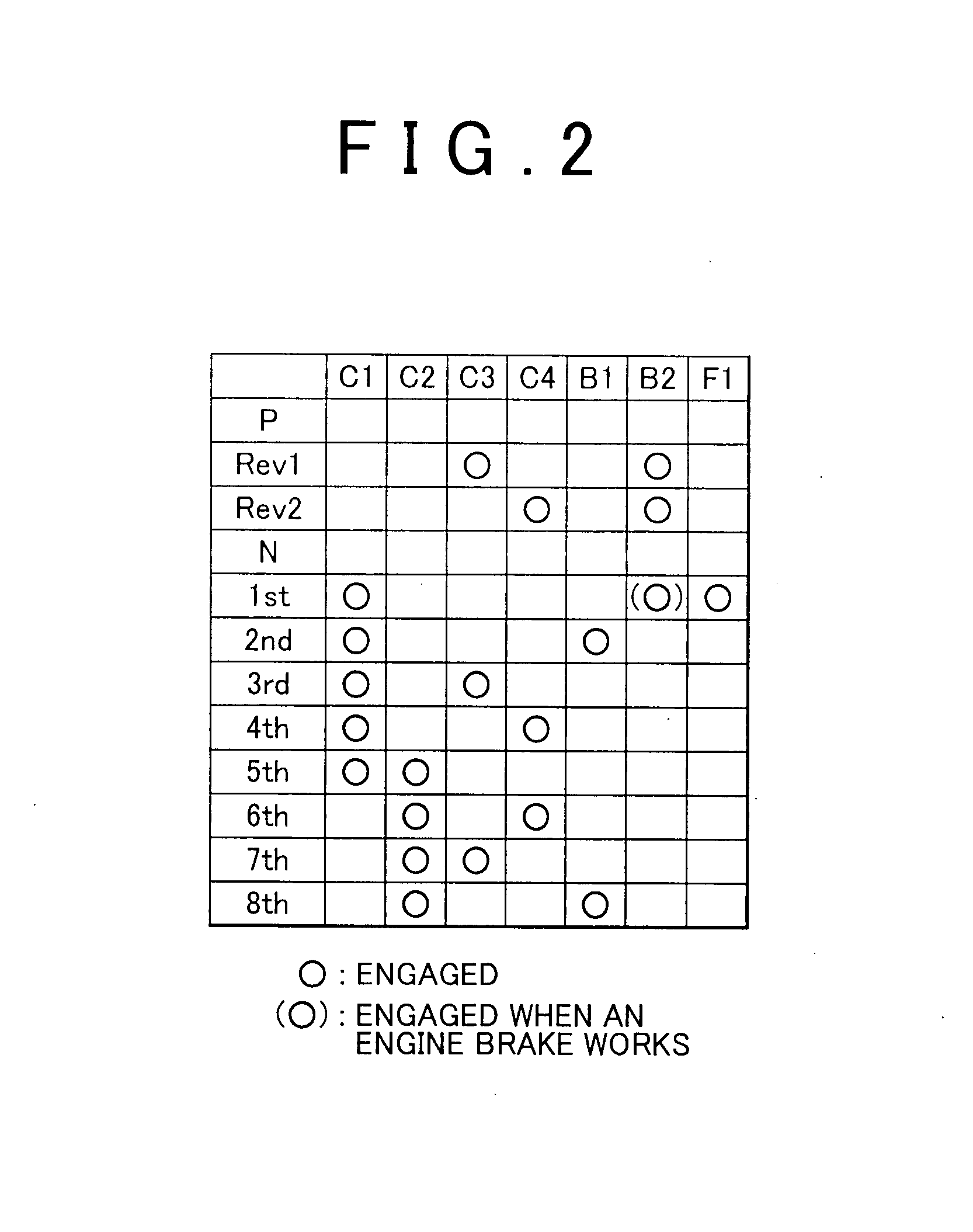
[0024]FIG. 1 is a skeleton diagram illustrating a configuration of an automatic transmission for use in a motor vehicle (hereinbelow referred to as an “automatic transmission”) 10 to which the present invention is applied. FIG. 2 is an operation table (engagement operation table) illustrating the operation combination of hydraulic friction engagement devices when a plurality of gear steps is established in the automatic transmission 10. The automatic transmission 10 includes a transmission case 32 serving as a non-rotating member attached to a vehicle body, a first transmission part 14 mainly composed of a double pinion first planetary gear set 12 and a second transmission part 20 mainly composed of a single pinion second planetary gear set 16 and a double pinion third planetary gear set 18, the first transmission part 14 and the second transmission part ...


PUM


Abstract

A hydraulic control system that includes a solenoid valve for supplying a prescribed fluid pressure; and a relay valve for selectively switching a destination of the prescribed fluid pressure between a first destination part and a second destination part. The relay valve has an input port supplied with a normally produced fluid pressure and an output port that selectively communicates with the input port. The hydraulic control system further includes a fluid pressure switch, provided in the output port of the relay valve, that is activated when the input port communicates with the output port to allow the normally produced fluid pressure to be supplied to the output port.

Description

INCORPORATION BY REFERENCE[0001]The disclosure of Japanese Patent Application No. 2006-307070 filed on Nov. 13, 2006 including the specification, drawings and abstract is incorporated herein by reference in its entirety.BACKGROUND OF THE INVENTION[0002]1. Field of the Invention[0003]The present invention relates to a hydraulic control system for use in a motor vehicle and a method for controlling the hydraulic control system, and, more particularly, to a hydraulic control system in which a solenoid valve that supplies a prescribed fluid pressure and a relay valve that selectively switches the destination of the prescribed fluid pressure are employed and a method for controlling the hydraulic control system.[0004]2. Description of the Related Art[0005]In conventional automatic transmission for a motor vehicle a plurality of gear steps of different speed ratios may be established by selectively engaging a plurality of hydraulic engaging devices. Japanese Patent Application Publication...

Claims


Application Information

Patent Timeline
Patent Type & Authority Applications(United States)
IPC IPC(8): F16H47/00F16D33/00F16H63/00F16K31/02F16H61/12F16H61/14F16H61/68F16H61/684F16H61/686
CPCF16H61/0206F16H61/12F16H61/143F16H61/686F16H2059/683F16H2061/1208F16H2200/006F16H2200/2048F16H2200/2097F16H2061/0288Y10T137/0396Y10T137/5987
Inventor NOZAKI, KAZUTOSHIOTA, HIROFUMIHONDA, ATSUSHI
Owner TOYOTA JIDOSHA KK
Why Eureka
Try Eureka