
Short-length reduced-pressure backflow preventor

A backflow prevention and angle technology, applied in the field of low-pressure backflow preventer valve assemblies, can solve the problems of high backflow preventer assembly manufacturing, assembly, maintenance and repair costs and other issues

Inactive Publication Date: 2005-07-27
CMB INDS
View PDF0 Cites 4 Cited by
  • Summary
  • Abstract
  • Description
  • Claims
  • Application Information

AI Technical Summary

Problems solved by technology

In general, it is believed that the assembly apparatus and method requiring the use of tools can result in relatively high fabrication, assembly, maintenance and repair costs of the backflow preventer assembly, and where there is limited interior volume available to accommodate tools, etc. ( such as is common in place-of-use applications) may not be feasible

Method used


Image

  • Short-length reduced-pressure backflow preventor
  • Short-length reduced-pressure backflow preventor
  • Short-length reduced-pressure backflow preventor

Examples


Embodiment Construction

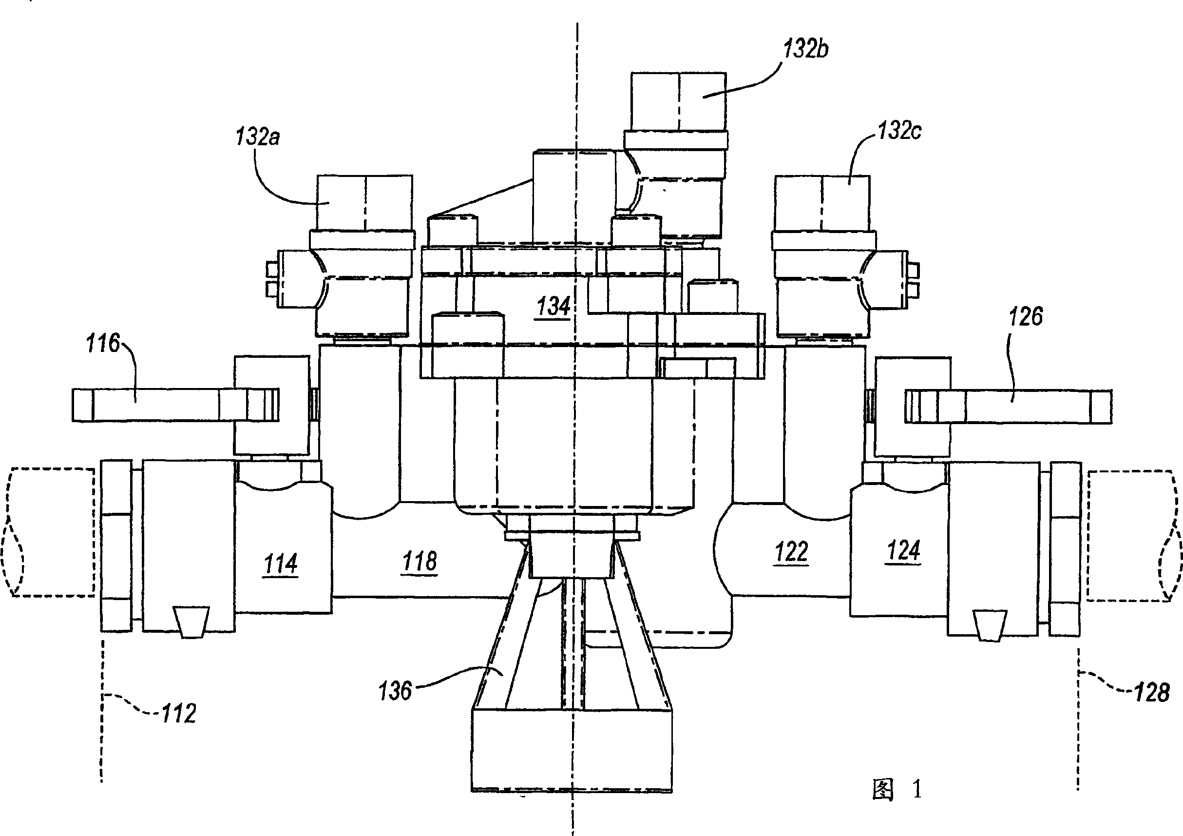
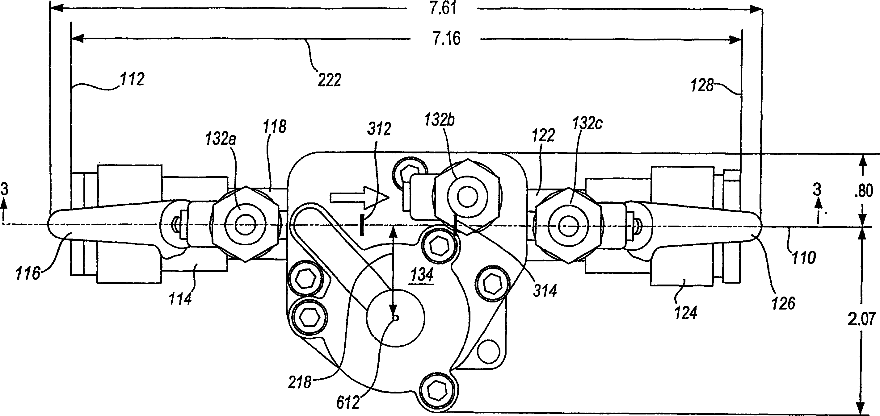
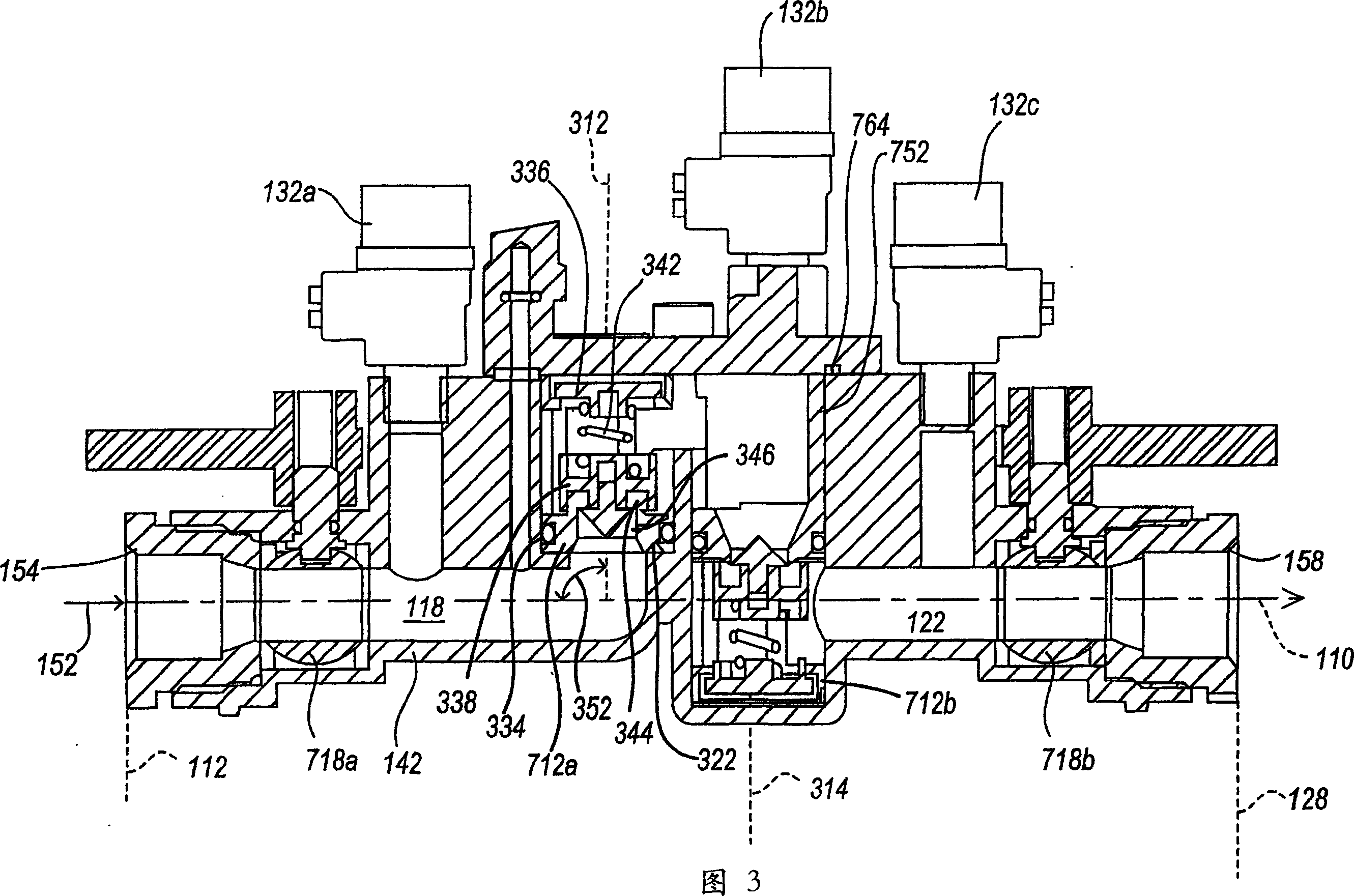
[0021] In the embodiment depicted in FIG. 1 , the input orifice forming an input orifice plane 112 is in fluid communication with a first shutoff valve body 114 controlled by a handle or lever 116 . Valve body conduit 118 provides fluid passage to a first check valve having a first check valve travel axis 312 (FIG. 3). The first check valve can be moved from the closed valve configuration shown in Figure 3 to the Figure 4 The normal open (that is, open during normal use) state among them. Liquid therethrough flows in a lateral direction 412 to a second check valve forming a second check valve axis 314 . Liquid flows through the second check valve and to a second conduit 122, which leads to a second shut-off valve body 124 controlled by a second lever or handle 126 whereby the liquid flow can pass through a plane 128 forming an output orifice. out of the output orifice. The test cocks 132a, b, c may be used for calibration, maintenance purposes and others. A relief valve m...


PUM


Abstract

A double check valve reduced pressure backflow preventor assembly is configured to have a relatively small length, volume and / or weight. The assembly defines parallel, preferably coaxial, inlet (112) and outlet (128) directions. In one aspect, axis (312) of first and the axis of second check valves are at an angle, preferably of 90 degrees, to the in-line axis (110). In one aspect, a relief valve (134) is positioned spaced from the in-line axis (110). First (718a) and second stop valves (718b) are enclosed in the same integral, unitary housing (142) which encloses the check valves and, preferably, some or all of the relief valve (134). The shutoff valves (718a, 718b) are preferably positioned along the in-line axis (110).

Description

technical field [0001] The present invention relates to a low-pressure backflow preventer valve assembly, and more particularly to a backflow preventer with a relatively small length. Background technique [0002] Backflow preventers are generally provided to allow water (or other liquid) to flow from a water source (such as a city water supply) to a supply location (such as a building) and ultimately to a point of use. However, a backflow preventer valve prevents the flow of liquid in the opposite direction (for example, to avoid contamination of municipal drinking water supplies, etc.). A number of configurations can be used to avoid backflow, including vacuum break systems and double check valve systems. In a double check valve system, fluid in normal use flows through the first (normally open) check valve into the area between the two check valves and then through the second (normally open) check valve . A relief valve connected to this area is normally closed. Durin...

Claims


Application Information

Patent Timeline
Patent Type & Authority Applications(China)
IPC IPC(8): E03B7/07F16K27/00E03C1/10F16K15/02F16K15/18
CPCF16K15/188F16K15/025E03B7/078E03B7/075E03B7/077Y10T137/6086Y10T137/0491Y10T137/7838F16K15/1848
Inventor 查尔斯·W·邓米尔
Owner CMB INDS
Learn More