Blast shielding

a shielding and blast technology, applied in the field of blast shielding, can solve the problems of unprovoked explosions, attendant loss of life of personnel in such buildings, and devastation, and achieve the effects of reducing damage, dissipating blast energy, and minimizing the injury of personnel

Active Publication Date: 2008-10-21
HIGH IMPACT TECH
View PDF7 Cites 23 Cited by
  • Summary
  • Abstract
  • Description
  • Claims
  • Application Information

AI Technical Summary

Benefits of technology

[0004]The just first-mentioned kind of curvature is referred to herein as curvature in a height manner, and the second-mentioned kind of curvature as curvature in a width manner. These curved strike-face portions act, with respect to an impinging blast shockwave, to engage and intercept that shockwave in such a fashion that laterally upwardly and downwardly curving deflection waves are created in such a way that damage will be significantly reduced relative to a protected structure, with minimized, associated personnel injury. In particular, the shield of the present invention responds to a striking blast shockwave by reversely deflecting substantially the entirety of the low-ground-level portions of such a shockwave upwardly and laterally outwardly, as we

Problems solved by technology

In recent years, and at different locations throughout the United States and in other countries, there have occurred terrorist-like activities involving the clandestine placement, typically in a vehicle, of high-energy explosive

Method used


Image

  • Blast shielding
  • Blast shielding
  • Blast shielding

Examples


Embodiment Construction

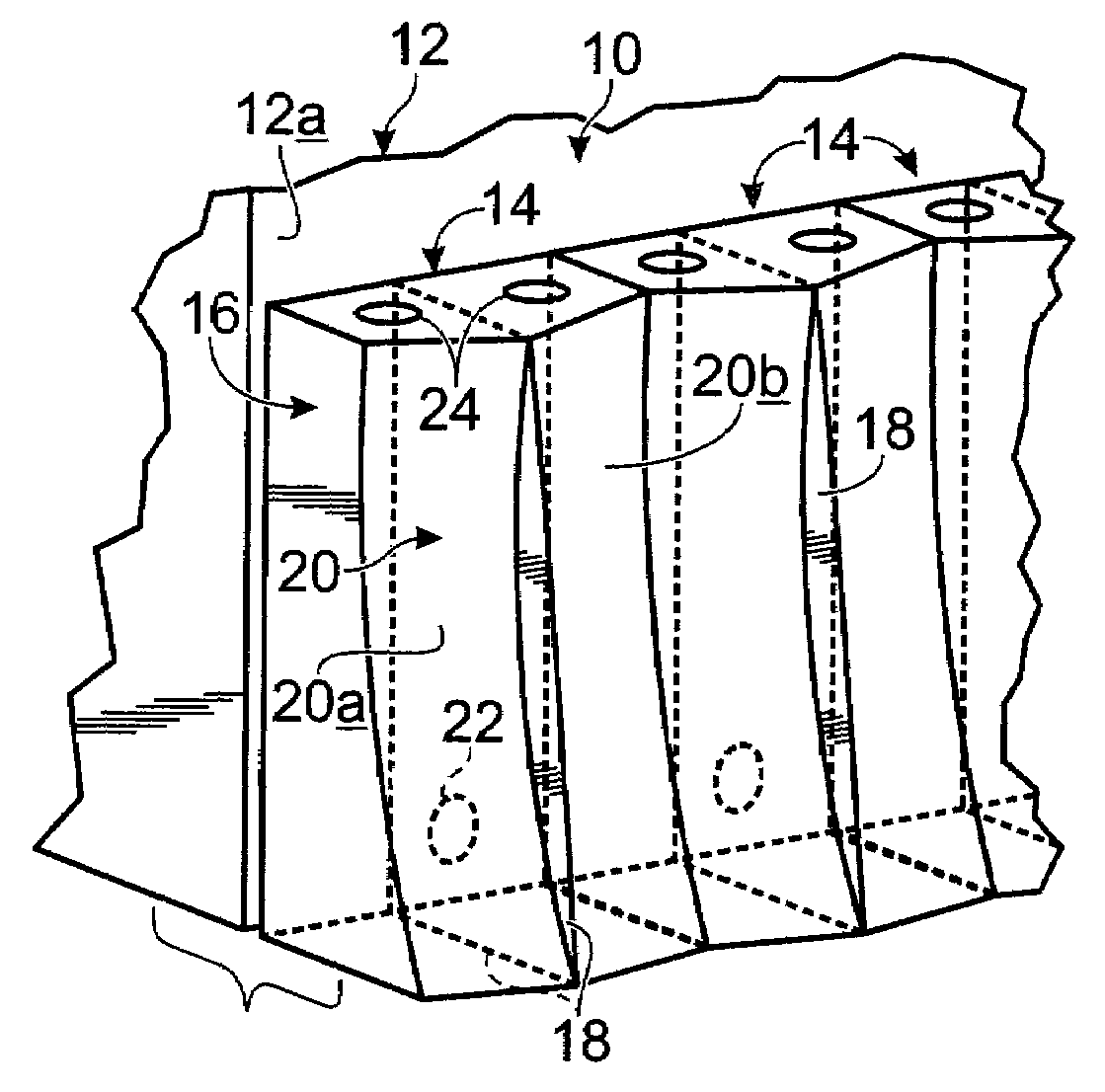
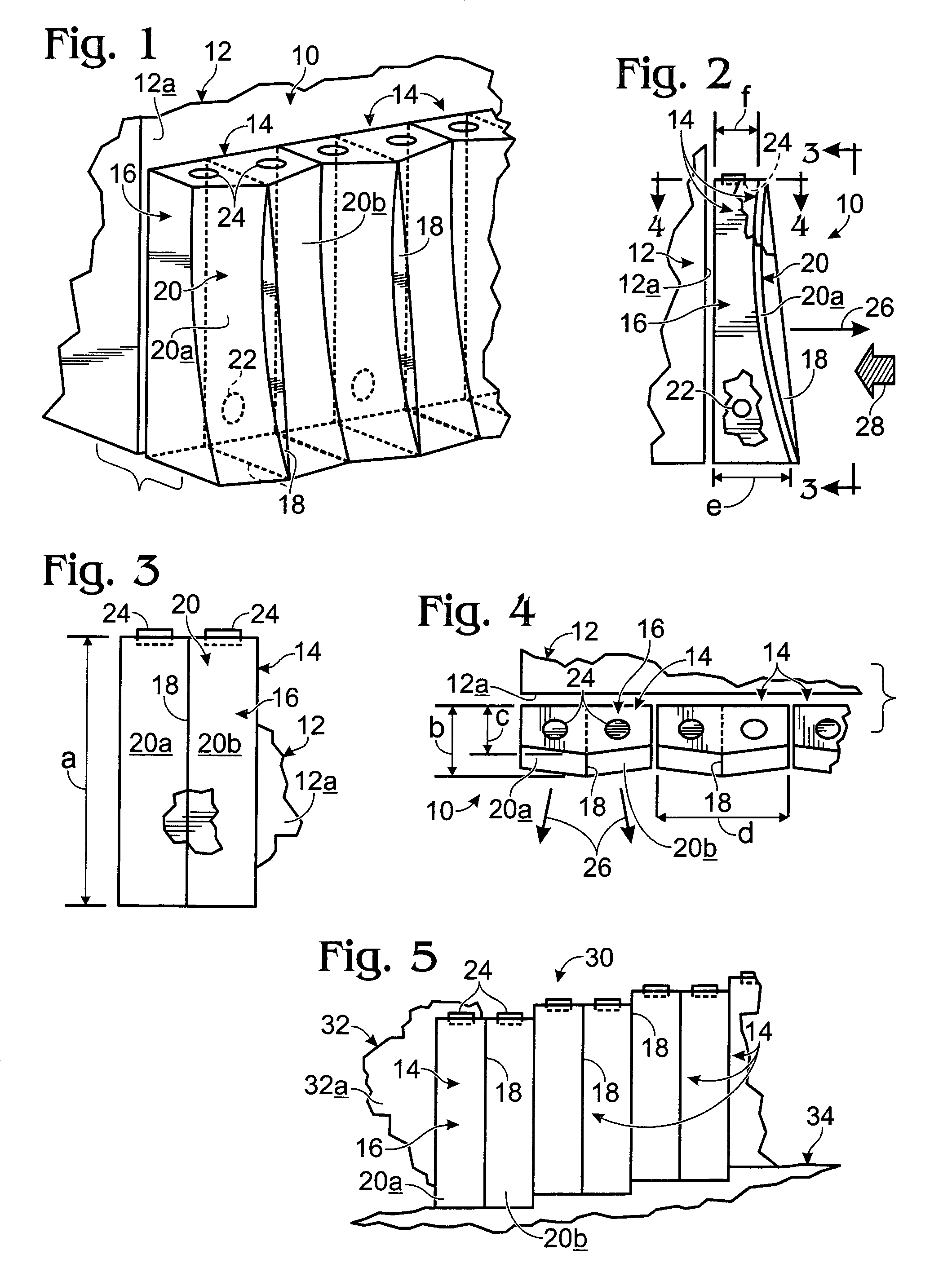
[0017]Turning now to the drawings, and referring first of all to FIGS. 1-4, inclusive, indicated generally at 10 in FIGS. 1, 2 and 4 is a soldier-course installation 10, spaced somewhat outwardly from the ground-level outside wall 12a of a building 12, of plural, side-by-side-adjacent, blast-protection shields 14, each of which has a generally upright, hollow, elongate, monolithic, sheet-steel body, such as body 16. Detailed description of each shield 14, all of them being alike, will now continue with reference just to one of the shields, and namely that one shield whose body 16 is specifically number-labeled in these three figures.

[0018]Each of shields 14 herein is designed, in the illustration now being given, to blast-protect a lateral portion of the ground-level region of outside wall 12a in building 12, with the entire soldier-course of these shields functioning to protect a long stretch of this wall. Each such shield has an overall height shown at a in FIG. 3 of about 12-feet...


PUM


Abstract

A blast shockwave shield including an upright, monolithic body having a lateral center, and front and back sides, and a blast-facing, curved strike face formed on the upright, front side of the body, including a pair of companion, laterally spaced, laterally symmetric, non-coextensive, curved, strike-face portions, each of which defines a blast shockwave-deflection vector that is aimed upwardly, and laterally outwardly away from the shield's lateral center. This structure implements a method for blast shockwave deflection which includes the steps of engaging and intercepting such a shockwave with an upright, monolithic, solid-resistance instrumentality having a pair of laterally spaced, curved, non-coextensive strike-face portions, and, by those acts of engaging and intercepting, reversely deflecting an impinging shockwave.

Description

CROSS REFERENCE TO RELATED APPLICATIONS[0001]This application claims priority to each of two, prior-filed, currently pending U.S. Provisional Patent Applications, including Application Ser. No. 60 / 721,371, filed Sep. 27, 2005 for “Blast Shroud and Method”, and Application Ser. No. 60 / 724,387, filed Oct. 6, 2005 for “Liquid Back-Spray Blast Shroud and Method”. The entire disclosure contents of these two provisional applications are hereby incorporated herein by reference.BACKGROUND OF THE INVENTION[0002]In recent years, and at different locations throughout the United States and in other countries, there have occurred terrorist-like activities involving the clandestine placement, typically in a vehicle, of high-energy explosives, near the outsides of buildings to create powerful and devastating, unprovoked explosions which have completely, or substantially, destroyed a target building with attendant loss of life regarding personnel in such a building. A great deal of preventive atten...

Claims


Application Information

Patent Timeline
IPC IPC(8): F41H5/24
CPCF42D5/045
Inventor OHNSTAD, THOMAS S.MONK, RUSSELL A.MARTIN, JOHN P.
Owner HIGH IMPACT TECH
Why Eureka
Try Eureka