Lighting device, image-reading device, color-document reading apparatus, image-forming apparatus, projection apparatus

a technology of image-reading device and light source, which is applied in the direction of lighting and heating apparatus, printing equipment, instruments, etc., can solve the problems of ineffective approach, limited use, and inconvenient use of light source for image-reading devi

Active Publication Date: 2008-10-21
RICOH KK
View PDF18 Cites 89 Cited by
  • Summary
  • Abstract
  • Description
  • Claims
  • Application Information

AI Technical Summary

Problems solved by technology

Although the current LEDs have the superior characteristics, absolute brightness of each of the elements is not sufficient so that they are not suited as a lighting device for an image-reading device.
Because of this drawback of the LEDs, their use is restricted to low-speed reading apparatuses and compactness-serious apparatuses.
However, since light of the LED array diffuses widely, this approach is not so effective.
Moreover, since the LED array consumes great power, this approach opposes the current energy-saving demands.
The figure depicts an example in which an equal-magnification sensor is used, and, for example, even when a 1 / 10 reduced image is formed by using a reduction optical system, the width of the illumination area on the document side to be image-formed on the single light-receiving unit 7 becomes only 1 millimeter at most, with the result that the same problems are raised.
However, since the premise of this arrangement is to use a rod-shaped light source, it is difficult to apply this method to LEDs having a size much smaller than this light source.
This difference causes differences in the distance between the light source and the illumination face and in the size of reflecting mirror.
The application of the same structure as that of FIG. 37 in an attempt to use an LED array fails to achieve the main objective for compensating for insufficient brightness of the LEDs since the light utilization efficiency is very low.
With this arrangement, the target luminance distribution is exemplarily obtained; however, a reflection plate is required in addition to the light-directing member so that the arrangement becomes more complex, resulting in the subsequent high costs.

Method used


Image

  • Lighting device, image-reading device, color-document reading apparatus, image-forming apparatus, projection apparatus
  • Lighting device, image-reading device, color-document reading apparatus, image-forming apparatus, projection apparatus
  • Lighting device, image-reading device, color-document reading apparatus, image-forming apparatus, projection apparatus

Examples


Embodiment Construction

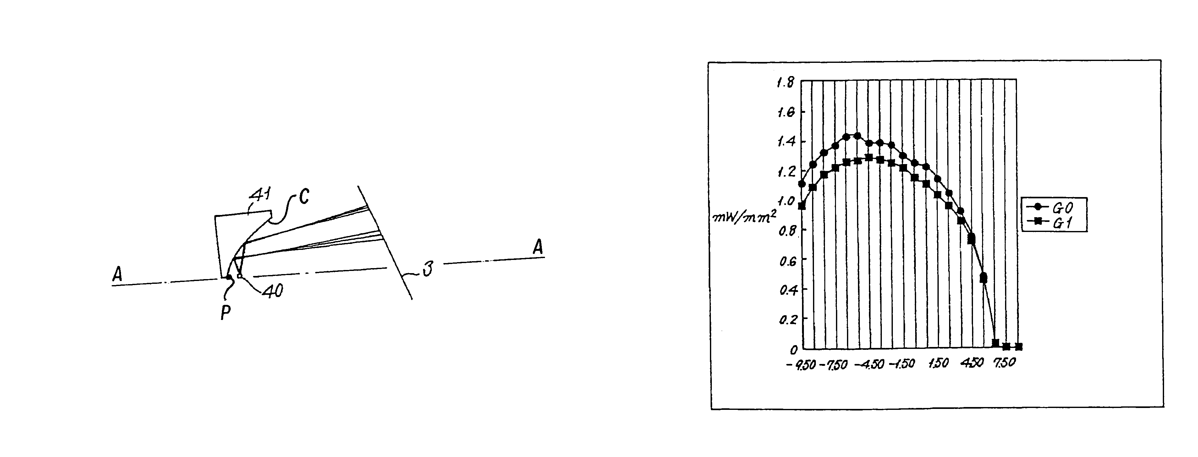
[0080]Exemplary embodiments of a lighting device, an image-reading device, a color-document reading apparatus, an image-forming apparatus, and a projection apparatus according to the present invention are explained below in reference to the accompanying drawings. However, before explaining of the embodiments (examples) of the present invention, the principle of the present invention will be explained first.

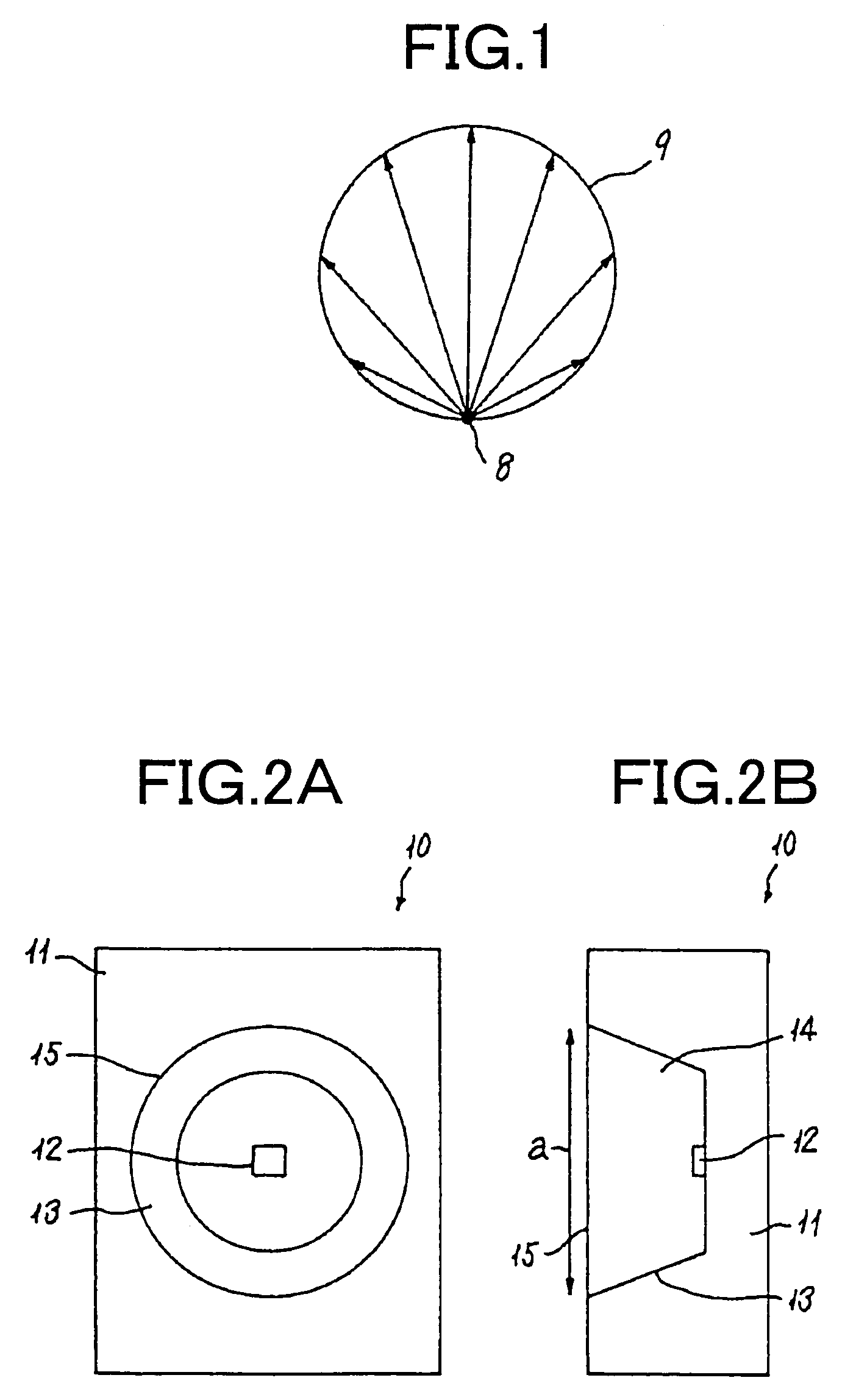
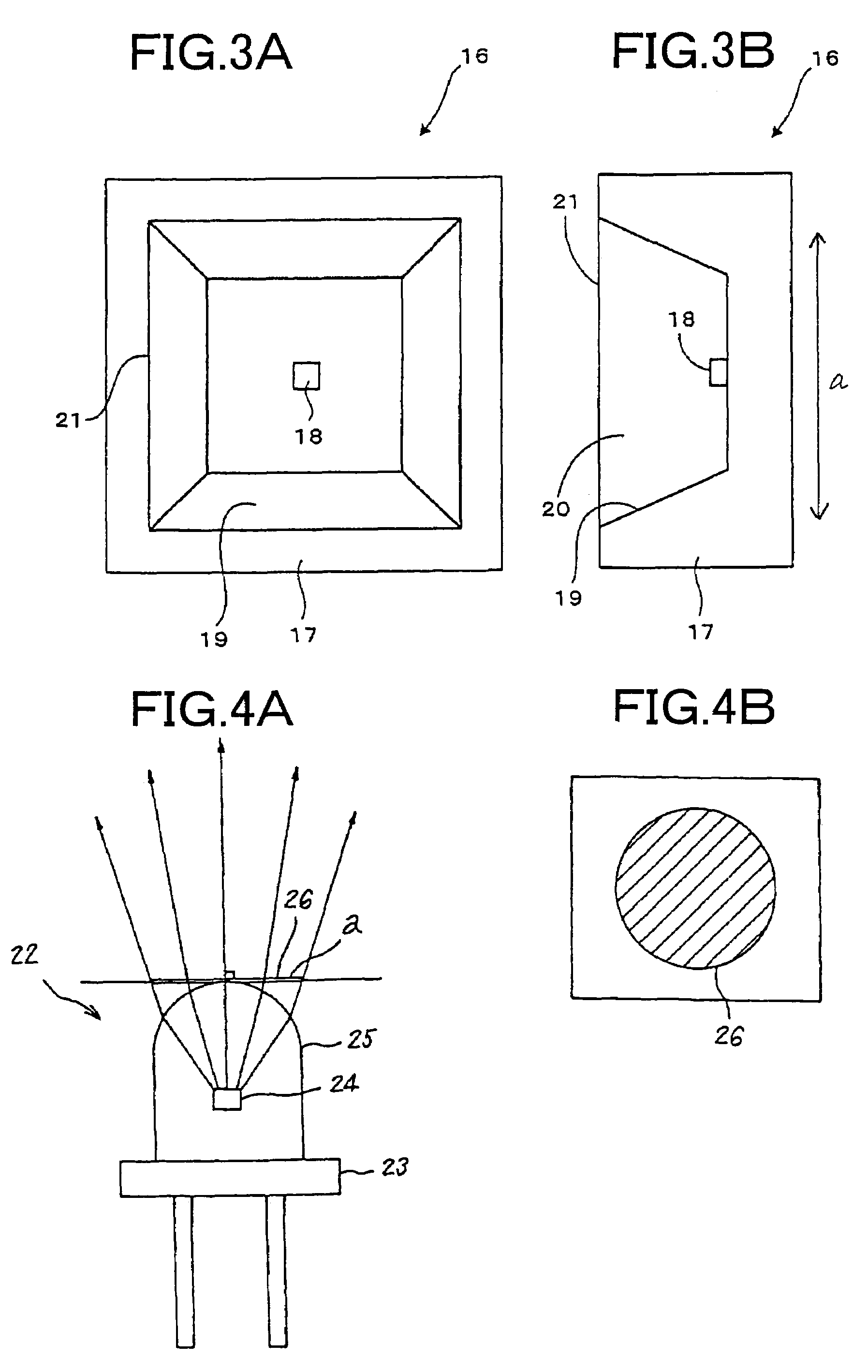
[0081]FIG. 1 depicts luminous intensity distribution of an LED, which is an example of a solid-state light-emitting element. The reference numeral 8 represents a point from where light is emitted (light-emitting point), and 9 represents a luminous intensity distribution in a cross section.

[0082]The luminous intensity distribution takes various forms depending on differences in characteristics of the emitter; however, in general, a luminous intensity distribution curve having a circular cross section is used to indicate the luminous intensity distribution. When the light-emitting p...


PUM


Abstract

A lighting device includes an illumination face having a length and a width; a light-emitting element having a light-ray-releasing face the maximum length of which is equal to or less than the width of the illumination face; and a light-source unit that has an optical element which changes the direction of light rays released from the light-emitting element to be directed to the illumination face. The optical element has a concave-face reflecting unit having a cross section that is shaped into a quadratic curve or a pseudo quadratic curve, which is placed at least on one portion thereof, and a luminance distribution on the illumination face has a flat portion that is equal to or not less than a predetermined width.

Description

CROSS-REFERENCE TO RELATED APPLICATIONS[0001]The present document incorporates by reference the entire contents of Japanese priority documents, 2003-329075 filed in Japan on Sep. 19, 2003 and 2003-389642 filed in Japan on Nov. 19, 2003.BACKGROUND OF THE INVENTION[0002]1) Field of the Invention[0003]The present invention relates to a document lighting device to be used for a reading apparatus, such as a digital copying machine, an image scanner and a digital laboratory.[0004]2) Description of the Related Art[0005]In recent years, the light emitting diodes (LEDs) have been researched actively. As a result of that, the LEDs are being made brighter and brighter. The LEDs have long service life, high efficiency, high G-resistant property, and they can emit light of one color. As a result, the LEDs are being used in many fields. The LEDs are used, for example, in document lighting devices in image-reading devices such as digital copying machines and image scanners.[0006]FIG. 36 is a schem...

Claims


Application Information

Patent Timeline
Patent Type & Authority Patents(United States)
IPC IPC(8): F21V7/00G02B9/34G03B27/54G06T1/00H01L33/50H01L33/58H01L33/60H04N1/028H04N1/04
CPCH04N1/02815H04N1/02825H04N1/0284
Inventor TATSUNO, HIBIKINISHINA, KIICHIRO
Owner RICOH KK
Why Eureka
Try Eureka