Snare drum strainer

a strainer and snare drum technology, applied in the field of snare drum strainers, can solve the problems of reducing the performance of the strainer, reducing the fluid movement of the strainer, and causing noise, so as to reduce the friction, enhance the fluid movement, and reduce the noise

Active Publication Date: 2008-10-21
K H S MUSICAL INSTR CO LTD
View PDF5 Cites 7 Cited by
  • Summary
  • Abstract
  • Description
  • Claims
  • Application Information

AI Technical Summary

Benefits of technology

[0019]The brake part makes use of the self-lubricating bearing and the shaft sleeve to generate a self-lubricating effect. In this way, when the suspender steady base is in use, friction can be reduced, so as to enhance the fluid movement and further reduce the noise. On the other hand, the pull handle driven part makes use of a bolt and a spacer to have the pull handle, the driven buttons and the driven pole pivotal coupled together. Therefore an operation for each component of the pull handle driven part can have an effortless and fluid movement, so as to effectively reduce the noise of the strainer.

Problems solved by technology

In this way, the strainer can not have a fluid movement and also may produce a noise.

Method used


Image

  • Snare drum strainer
  • Snare drum strainer
  • Snare drum strainer

Examples


Embodiment Construction

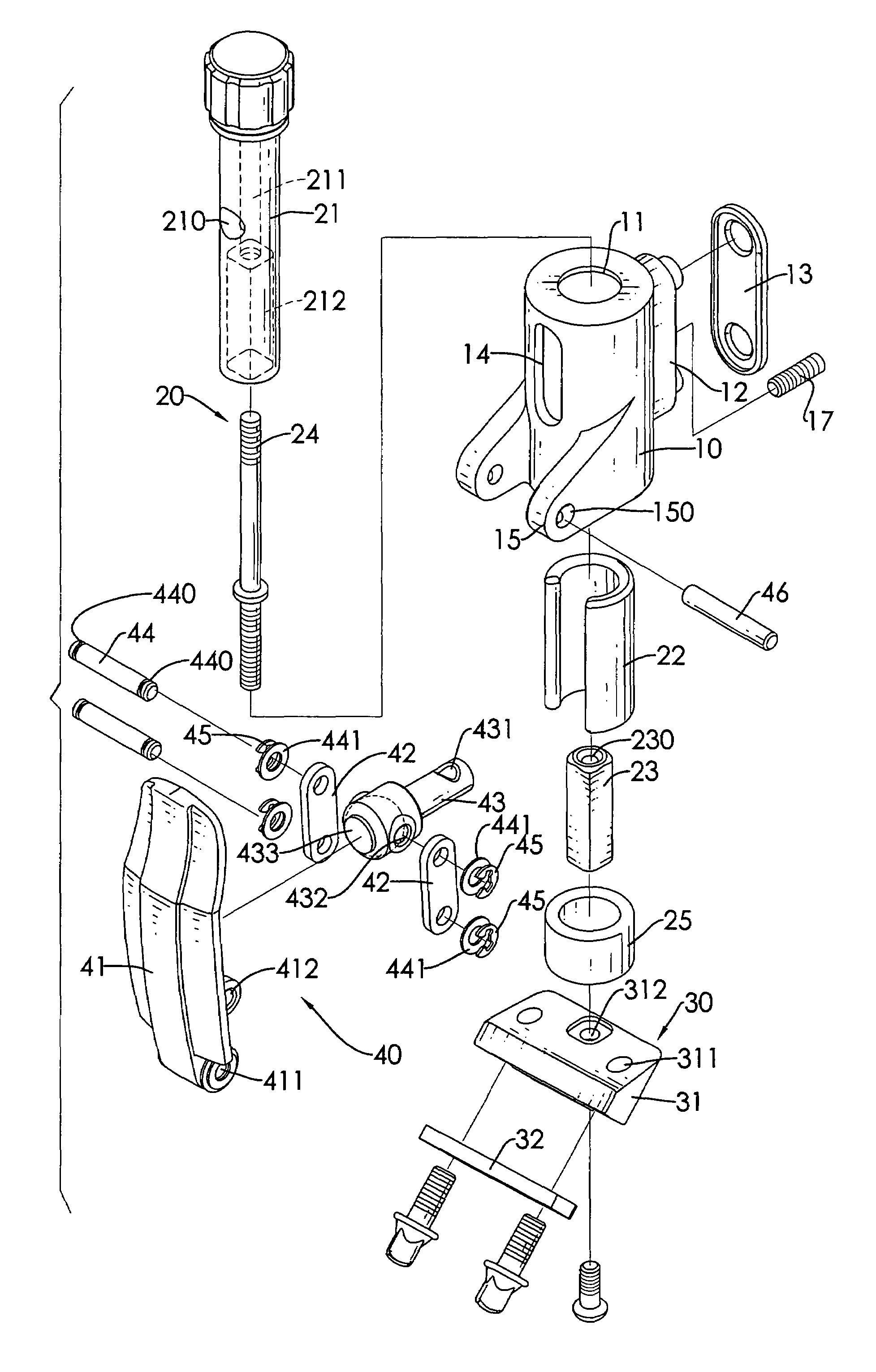
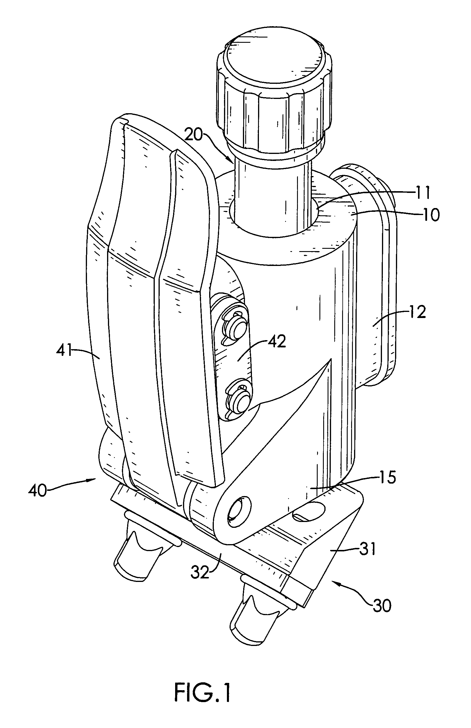
[0026]With reference to FIG. 1, an external appearance diagram of a snare drum strainer of a preferred embodiment in accordance with the present invention has a switch stand 10, a brake part 20, a suspender steady base 30 and a pull handle driven part 40. The brake part 20 slides inside the switch stand 10 and also moves upward and downward. The suspender steady base 30 is steady located at a lower end of the brake part 20 for clipping multiple snares. The pull handle driven part 40 is pivotally coupled to the switch stand 10 for controlling the brake part 20 to be ascending and descending.

[0027]With reference to FIGS. 2 and 3, the switch stand 10 forms a hollow cylindrical shape. A top of the switch stand 10 defines an opening 11 and a bottom of the switch stand 10 is of an open form. An elliptic steady part 12 extending outward is formed on a first external sidewall of the switch stand 10. A steady plate 13 is connected to the steady part 12, so the steady part 12 fastens to a dru...


PUM


Abstract

A snare drum strainer includes a switch stand, a brake part, a suspender steady base and a pull handle driven part. The brake part can slide inside the switch stand and also can move upward and downward. The suspender steady base is steady located at a lower end of the brake part for clipping multiple snares. The pull handle driven part is pivotally coupled to the switch stand for controlling the brake part to be ascending and descending. The brake part makes use of a self-lubricating bearing and a shaft sleeve to generate a self-lubricating effect. Further, the pull handle driven part makes use of a bolt and a spacer to have the pull handle, the driven buttons and the driven pole pivotal coupled together. When the suspender steady base is in use, friction can be reduced, so as to enhance the fluid movement and further reduce the noise.

Description

BACKGROUND OF THE INVENTION[0001]1. Field of the Invention[0002]The invention relates in general to a snare drum strainer, and more particularly to a snare drum strainer that can have an effortless and fluid movement, so as to effectively reduce a noise of the strainer.[0003]2. Description of the Related Art[0004]With reference to FIG. 5, a conventional snare drum includes a cylindrical shell 70 made of wood, metal or plastic etc. material, drum heads 71, multiple snares 72 and a side-throw strainer. The drum heads 71 are stretched across both openings of the drum's shell 70. The snares 72 are stretched across the bottom drum head 71. When the top of the drum head 71 is struck, causing a sudden increase in pressure within the instrument, the snares 72 vibrate against the bottom head 71. This produces a short, distinctive and snap-like sound. The snares 72 can be disengaged if this effect is not wanted. The side-throw strainer 80 with dual fine adjustment on the throw and butt side a...

Claims


Application Information

Patent Timeline
Patent Type & Authority Patents(United States)
IPC IPC(8): G10D13/02
CPCG10D13/025G10D13/02G10D13/18
Inventor HSIEH, WU-HONG
Owner K H S MUSICAL INSTR CO LTD
Why Eureka
Try Eureka