Monoblock valveless opposing piston internal combustion engine

Active Publication Date: 2010-11-11
TWO HEADS
View PDF17 Cites 50 Cited by
  • Summary
  • Abstract
  • Description
  • Claims
  • Application Information

AI Technical Summary

Benefits of technology

[0012]The present invention provides an internal combustion engine that can be, in embodiments, characterized as a horizontally arranged multi-cylinder monoblock-type engine having opposed piston pairs in a monochamber, wherein both pistons share the same combustion chamber. The engine can carry out all of the stages required of an internal combustion engine per crankshaft rotation. That is, the engine is capable of making an explosion per cylinder, at identical intervals, for each crankshaft rotation. In preferred embodiments, the spark plugs are directly in the upper dead-center position of one of the pistons, referred to as the admission piston, with each cylinder comprising one or two spark plugs per cylinder. In embodiments, one or more spark plugs may be removed, and the spark plug port used as a port for connecting a hollow chamber, which allows the compression ratio of the engine to be adjusted or modified as needed, for example, for different fuels.
[0033]Likewise, the exit ports can be connected to each other and to a single conduit for movement of fluids. For example, the exhaust ports can be connected by way of a generally circular or generally spiral conduit, which links the exhaust ports to each other and to a means for expelling exhaust gas from the engine (e.g., an exhaust system). The shape and number of intake and exhaust ports are preferably designed in conjunction with the shape of the respective conduits to improve fluid movement into and out of the cylinder. For example, intake ports and conduits may be designed to provide superior mixing of air and / or fuel within the combustion chamber. Likewise, exhaust ports and conduits may be designed to provide rapid and substantial removal of fluids (e.g., exhaust) from the combustion chamber and to dissipate heat.

Problems solved by technology

For example, various engines with piston arrangements or sets that work face-to-face are known in the art, but none of those engines manages to optimize its operation to obtain a complete cycle engine.

Method used


Image

  • Monoblock valveless opposing piston internal combustion engine
  • Monoblock valveless opposing piston internal combustion engine
  • Monoblock valveless opposing piston internal combustion engine

Examples


Embodiment Construction

[0055]Reference will now be made in detail to various exemplary embodiments and features of the invention, examples of which are illustrated in the accompanying drawings. The following detailed description is provided to give the reader a more thorough understanding of certain features of the invention, and should not be considered as a limitation on any aspect of the invention.

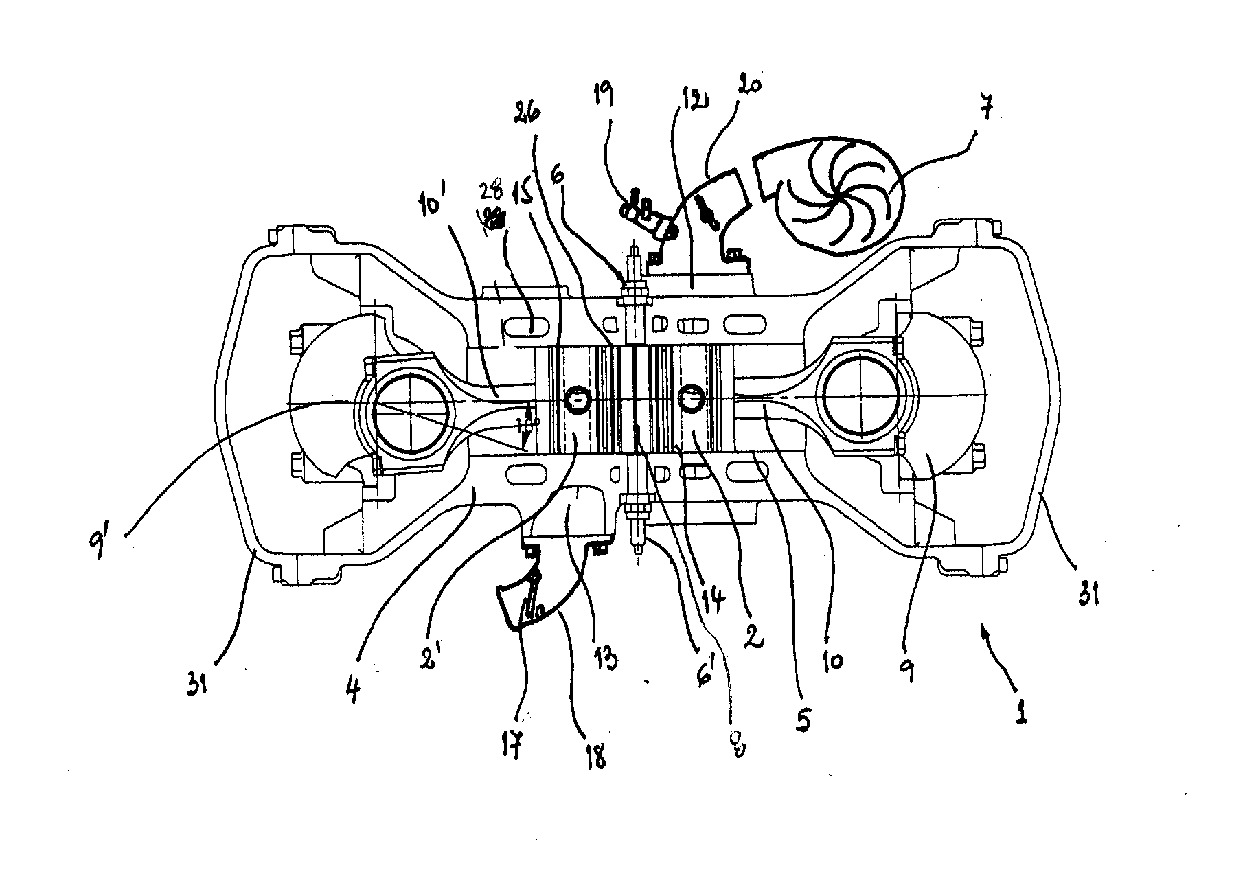
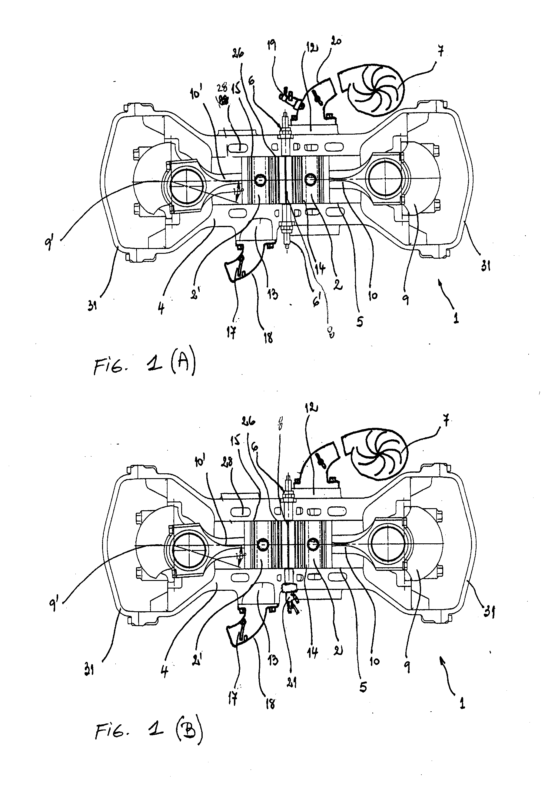
[0056]The internal combustion engine of the present invention has numerous features and combinations of features that provide improvements in fuel efficiency, power generation, adaptability, and other beneficial improvements, as compared to commercially available engines. One notable feature includes dual-action pistons, which act as both pistons for transfer of explosive energy from the combustion of fuel to mechanical energy, and as valves for opening and closing of intake and exhaust ports for fuel and exhaust, respectively. Unlike known two-stroke engines, which use pistons to open and close ports, but wh...


PUM


Abstract

The present invention provides an internal combustion engine that provides advantages of both typical 2-stroke engines and typical 4-stroke engines, but using a new design unlike either. The present engine provides for use of pistons as means for opening and closing intake and exhaust ports disposed on cylinder walls. It also provides two pistons per cylinder in an opposing configuration, such that one fuel explosion event causes motion of both pistons per cylinder, in opposite directions. Each piston of a cylinder is connected to a separate crankshaft, which completes a single revolution about its axis per fuel explosion event in a cylinder. In a single cycle of piston movement along the cylinder, a full cycle of ignition, exhaust, intake, and compression is achieved.

Description

CROSS-REFERENCE TO RELATED APPLICATIONS[0001]The present application relies on, and claims the benefit of the filing date of, U.S. provisional patent application No. 61 / 002,380, filed 8 Nov. 2007, and U.S. provisional patent application No. 61 / 082,378, filed 21 Jul. 2008, the entire disclosures of both of which are hereby incorporated herein by reference.BACKGROUND OF THE INVENTION[0002]1. Field of the Invention[0003]The present invention relates to the field of internal combustion engines. More specifically, the present invention relates to a five-cycle internal combustion engine that is suitable for use as both a gasoline engine and a diesel engine, having an improved design that allows for improved fuel efficiency and improved power production.[0004]2. Description of Related Art[0005]Internal combustion engines are known in the art. For example, various engines with piston arrangements or sets that work face-to-face are known in the art, but none of those engines manages to optim...

Claims


Application Information

Patent Timeline
IPC IPC(8): F02B25/08
CPCF01B3/10F01B7/14F02B75/282F02B61/04F02B2023/085F02B2075/028F02F1/186F02B75/32Y02T10/12
Inventor ALONSO, JOSE LUIS
Owner TWO HEADS
Why Eureka
Try Eureka