Aerosol refill cartridge

a technology of aerosol and refill cartridge, which is applied in the direction of liquid transferring devices, instruments, sustainable manufacturing/processing, etc., can solve the problems of difficult to deliver and dispense thick and/or viscous materials, damage to pumping equipment, and prior known material management systems have encountered difficulties in transferring from containment vessels, etc., to achieve the effect of improving the efficiency of fluid transfer operation, improving fluid movement into and out of the system, and saving energy

Active Publication Date: 2014-07-31
CH & I TECH INC
View PDF9 Cites 9 Cited by
  • Summary
  • Abstract
  • Description
  • Claims
  • Application Information

AI Technical Summary

Benefits of technology

[0012]The system's wetted surfaces, i.e. the interior surfaces that come in contact with the viscous fluid, can be treated to improve the efficiency of the fluid transfer operation. That is, the movement of the fluid into and out of the system can be improved by selective application of treatments to the interior surfaces and / or the fluid itself. The interface between a moving fluid and a surface creates a boundary layer, which is more pronounced in highly viscous fluids than less viscous fluids. At the surface of the wall, the fluid will have a zero velocity and assume the wall temperature, whereas at some point spaced from the wall the fluid will assume the bulk fluid temperature and move at the bulk fluid velocity. In between these two conditions is the boundary layer, which affects the energy required to move the fluid. A viscous fluid will have a larger boundary layer and thus be more greatly affected by the characteristics of that boundary layer. In the present system, a cylindrical (or other shaped) vessel moving viscous fluid axially will be governed by the conditions at the wall of the vessel.
[0013]One condition that significantly affects the boundary layer, and thus the fluid flow, is the surface roughness of the wall. Roughness is a major factor in boundary layer analysis, where a rougher surface increases the boundary layer and requires more energy to move the same amount of fluid, whereas a smoother surface reduces the boundary layer and reduces the amount of energy required to move the fluid within the vessel. The present invention takes advantage of this phenomenon to adjust the surface roughness of the surface of the wall by treating the wall with a material selected to diminish surface roughness and create an interface between the viscous fluid and the wall surface. The material may be applied to any and all wetted surfaces within the vessel, including the force transfer device, so that fluid will move more efficiently through the system. Alternatively, the surface of the inner walls of the vessel (and the force transfer device) can be modified to manipulate the boundary layer that forms at the interface of the fluid and the surfaces. Polishing, abrading, pitting, and microfinishing are all modes by which the boundary layer within the vessel can be modified or controlled to improve the fluid transfer operation.

Problems solved by technology

Prior known material management systems have encountered difficulty transferring from a containment vessel certain thick, viscous fluids, liquids and other types of materials that may resist pumping and that can be damaging to pumping apparatus.
Delivering and dispensing thick and / or viscous materials presents a challenge because these materials resist flowing and are not easily dispensed or moved out of their containers.
These devices, however, are highly susceptible to disruption if the sidewalls of the viscous material container become out-of-round or dented.
Moreover, some systems require high precision in all its parts, and require relatively bulky and expensive equipment.
Moreover, the pump and follower plate are connected or otherwise coupled so as to increase the expense and mechanical sophistication of such material transfer systems.
Heretofore known vessels and containers were basic moderate-high-pressure vessels having characteristics that were deficient in transferring difficult to move materials.
Such containers also were susceptible to internal rusting, and often were closed, and therefore difficult to clean.
These follower devices were difficult to fabricate, relatively expensive, rust-prone and could not wipe the vessel walls, even if desired by the user.
Many such systems contained heavy “ballast” that was not modifiable after fabrication and were easily canted (tipped) if container was placed on its side.
However, the disclosed container is configured as a vertical, closed, pressure vessel that may be difficult to clean.
Moreover, the disclosed boat is a single-function (prevents gas bypass), heavy, difficult to manufacture apparatus.

Method used


Image

  • Aerosol refill cartridge
  • Aerosol refill cartridge
  • Aerosol refill cartridge

Examples


example no.1

EXAMPLE NO. 1

Automotive Body Sealant Dispenser

[0066]Dispensing volume: 1.9 gallons (432 cubic inches, 7.1 liters)

Container

[0067]Top: flat[0068]Bottom: flat[0069]Inside Diameter: 6.5 inches (16.5 cm)[0070]Inside height: 14.5 inches (36.8 cm)[0071]Flooded volume: 2.1 gallons (481 cubic inches, 7.9 liters)[0072]Material: aluminum

Force Transfer Device

[0073]Top: flat[0074]Bottom: 120 degree cone[0075]Bottom protuberance: none[0076]Tangential diameter: 6.25 inches (15.9 cm)[0077]Tangential height: 1.0 inches (2.5 cm)[0078]Material: aluminum

example no.2

EXAMPLE NO. 2

Automotive Body Sound Deadening Dispenser

[0079]Dispensing volume: 21.7 gallons (5,013 cubic inches, 82.1 liters)

Container

[0080]Top: 2:1 semi-ellipsoidal[0081]Bottom: 2:1 semi-ellipsoidal[0082]Inside Diameter: 15.5 inches (39.4 cm)[0083]Straight shell height: 32.1 inches (81.5 cm)[0084]Flooded volume: 34.3 gallons (7,929 cubic inches, 129.9 liters)[0085]Material: stainless steel

Force Transfer Device

[0086]Top: 2:1 semi-ellipsoidal[0087]Bottom: 2:1 semi-ellipsoidal[0088]Bottom protuberance: diameter of 3.0 inches (7.6 cm) and height of 2.5 inches (6.4 cm)[0089]Tangential diameter: 14.0 inches (35.6 cm)[0090]Tangential height: 5.0 inches (12.7 cm)[0091]Material: stainless steel

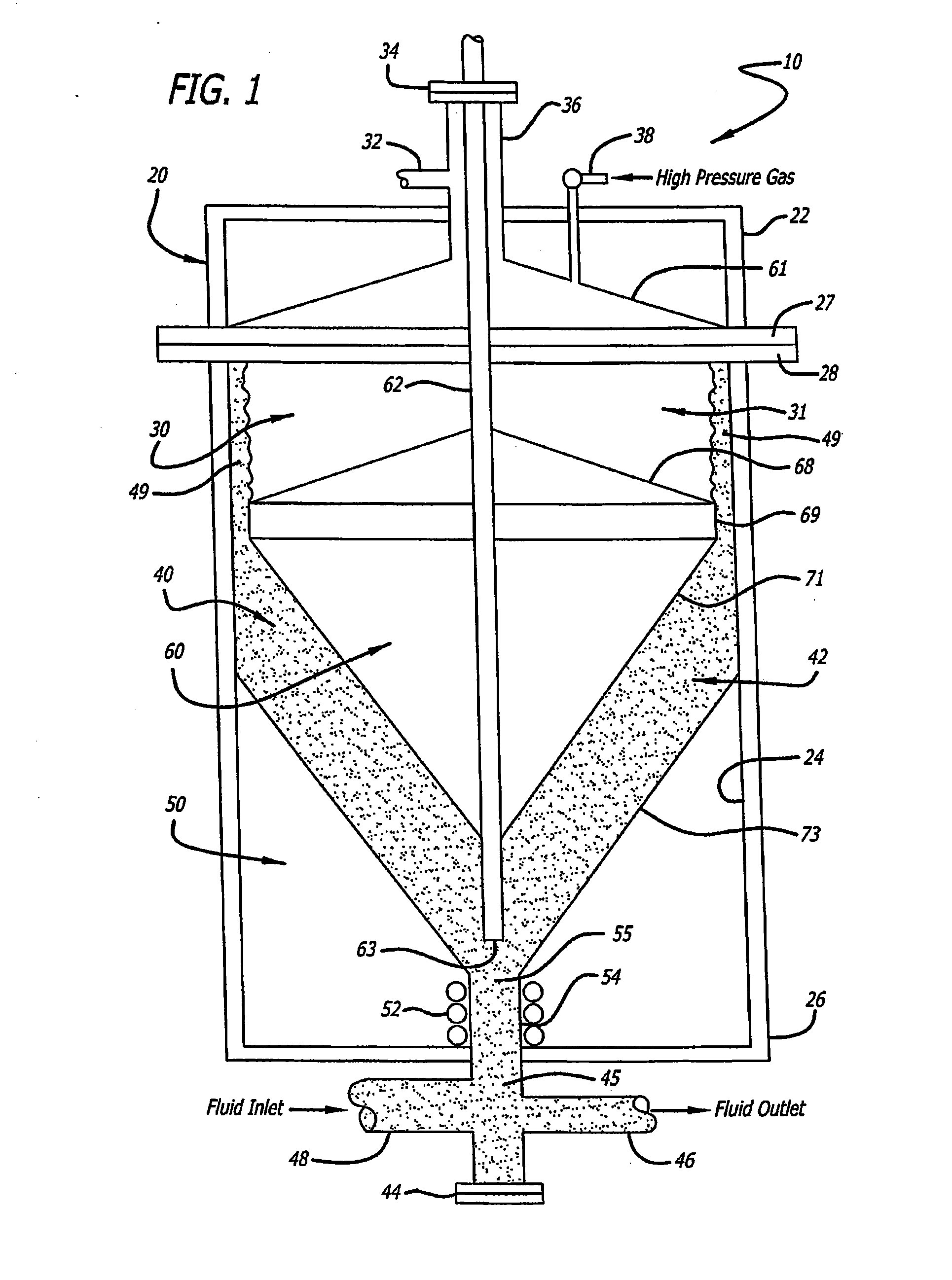
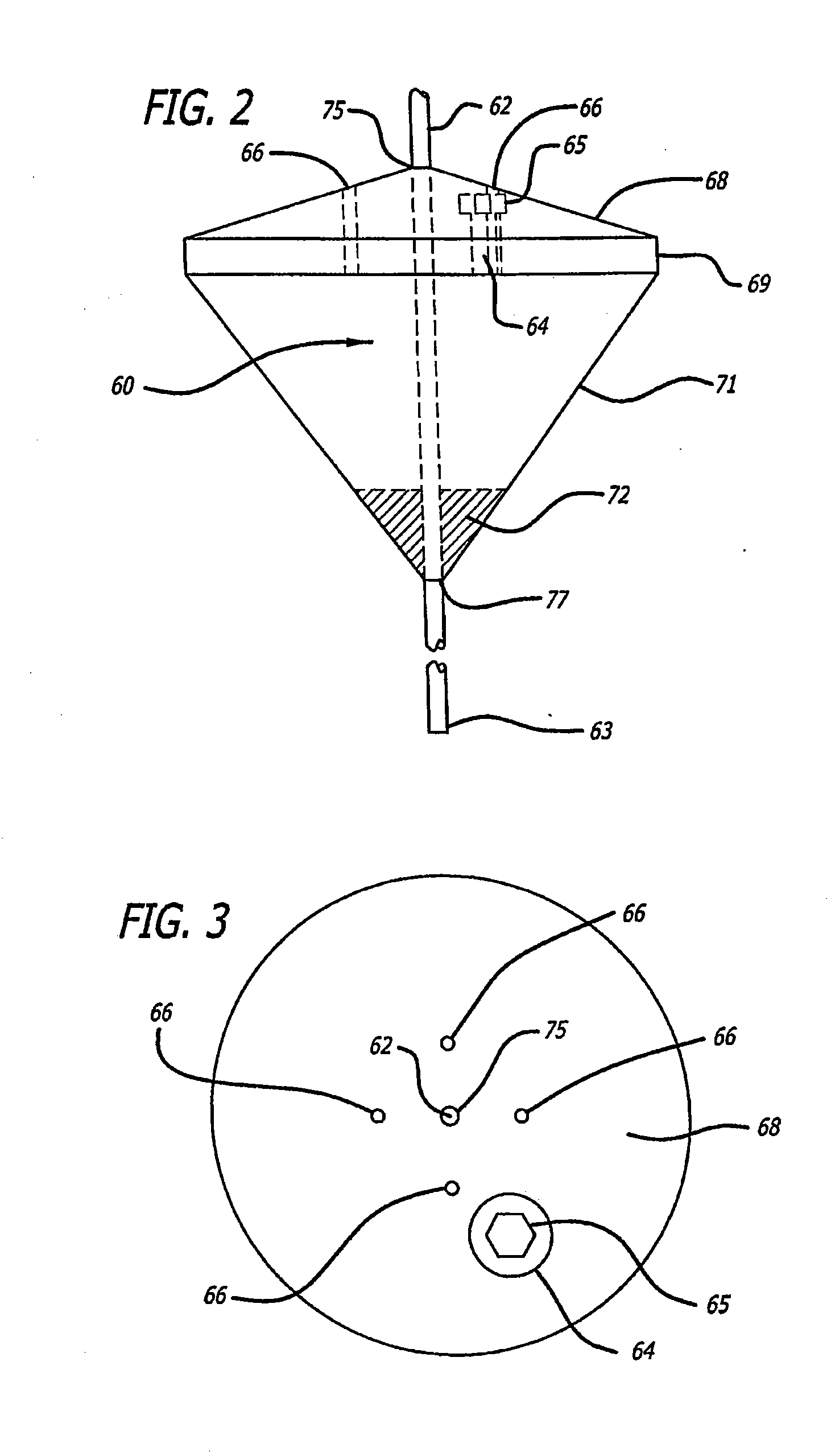
[0092]Proximity of the tangential member 69, 95, 230, 232, 234, 236, 330, 332, 334, 346, 348 of the force transfer device 60, 90, 200 and 300 to the sidewall 24 of the material container 20, 120 is dependant, among other things, upon the nature of the material 42. The proximity range from 0.2 to 1.0 i...


PUM


Abstract

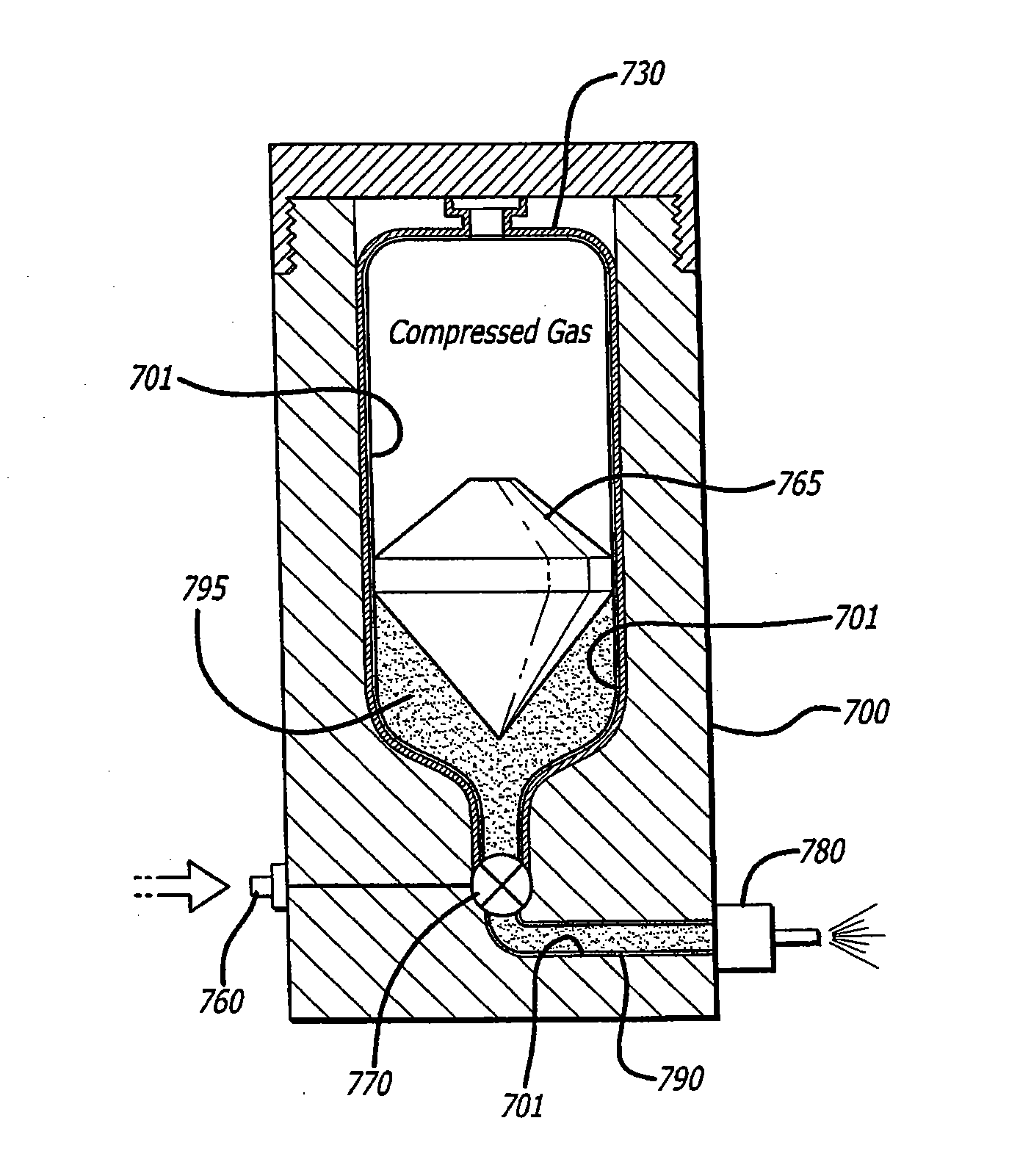
An apparatus for dispensing material through a refillable cartridge, comprising a container having a receptacle for receiving a refill cartridge, the container having a lid cooperating with the container to enclose the refill cartridge, the container further comprising an exit port and a channel for communicating material from the refill cartridge to the exit port, and a valve for controlling the flow of material out of the refill cartridge; and a reusable, refill cartridge sized to be received in the receptacle, the refill cartridge including compressed gas and material separated by a bi-conical thruster, the refill cartridge further comprising a first end having a material inlet and outlet manifold, and a second end having a compressed gas inlet. The system's performance can be improved by applying a surface treatment to the wetted surfaces of the system to change the physical properties at the fluid/vessel interface.

Description

CROSS-REFERENCE TO RELATED APPLICATION[0001]This application claims the benefit of U.S. patent application Ser. No. 13 / 222,604, filed Aug. 31, 2011, which in turn claims the benefit of U.S. patent application Ser. No. 12 / 426,789, filed Apr. 20, 2009, now U.S. Pat. No. 8,413,856; which in turn claims the benefit of U.S. Provisional Application Ser. No. 61 / 124,913, which in turn claims the benefit of U.S. patent application Ser. No. 11 / 096,356, filed Mar. 31, 2005, now U.S. Pat. No. 7,997,445 which in turn claims the benefit of U.S. Provisional Application Ser. No. 60 / 558,691, the contents of which are hereby incorporated herein by reference.BACKGROUND OF THE INVENTION[0002]The present invention relates to the field of materials management, and more particularly to systems designed for containing, transferring, delivering and dispensing various materials. The material management system of the invention is configured to deliver contamination free streams from a vessel that can be empti...

Claims


Application Information

Patent Timeline
Patent Type & Authority Applications(United States)
IPC IPC(8): B65D83/38
CPCB65D83/384B05B9/0838B65D83/425B65D83/64G01F11/021G01F11/04Y02W30/80B65D83/38
Inventor LEVENSTEIN, LAWRENCE M.THIBODEAU, ROBERT D.WILLIAMS, ERIC A.
Owner CH & I TECH INC
Why Eureka
Try Eureka