Thermoluminescence measurements and dosimetry with temperature control of the thermoluminescent element

a technology of thermoluminescent elements and measurements, applied in the field of dosimeter systems, can solve the problems of insufficient reproducibility of this method, complex and expensive whole system, and inability to accurately measure the temperature of the thermoluminescent element, etc., to achieve fast, accurate and reproducible, and facilitate tl measurements.

Active Publication Date: 2008-10-21
KATZIR ABRAHAM
View PDF16 Cites 1 Cited by
  • Summary
  • Abstract
  • Description
  • Claims
  • Application Information

AI Technical Summary

Benefits of technology

[0024]A system of the present invention includes a TLD element that stores energy when exposed to ionizing radiation, and releases the energy in the form of luminescent light when heated. In some embodiments, the system includes a laser whose energy is used to heat the element. In other embodiments, the heat is provided by a non-laser heating source. The heated element emits radiation in two spectral ranges: thermal infrared (IR) radiation, whose intensity is determined by the temperature of the element, and visible (or near-infrared or UV) luminescence. The system further includes an IR radiometer (i.e. thermometer), which measures the emitted thermal infrared radiation, and generates a signal which is measured by known means, e.g. a computer. A computer program or similar analyzing means uses the signal to determine the temperature of the element and to control the laser power so that a desirable temperature is obtained. The computer program can vary the temperature as a function of time. The rapid response of the system makes it possible to control the heating rate of the element and to generate a desired heating scheme, such as linear heating or exponential heating. The system also includes a photodetector for measuring the luminescence emitted during the heating of the element. The signal generated by the photodetector is also measured by the computer, and a plot of the emitted intensity as a function of the temperature (i.e. a glow curve) is obtained. The computer program analyses the glow curve and determines the total radiation dose to which the element had been exposed.
[0025]The system and method disclosed herein facilitate TL measurements under tight temperature control of the TLD element itself (for example using a laser beam). This makes it possible to heat the elements linearly, even with a fast heating rate. The measurement of the glow curve is therefore fast, accurate and reproducible. This, in turn, provides highly accurate and reliable thermoluminescence dosimetry.
[0043]According to the present invention there is provided a TL-based dosimetry system comprising: at least one TLD element operative to be heated controllably and to emit luminescence during the heating; a laser for effecting the heating; an infrared detector for monitoring IR radiation emitted from each TLD element during the heating and for providing respective IR radiation inputs used in the controllable heating; a TL detector for obtaining luminescence readings, the luminescence readings correlated with a radiation dose to which the element has been exposed; and a controller for controlling the laser based on the IR radiation inputs, thereby facilitating the controllable heating of each TLD element
[0048]According to another feature in the method of the present invention, the step of performing TL measurements and the obtaining of IR temperature readings includes using respective optical fibers to respectively transmit laser radiation, TL emission radiation and IR radiation, thereby allowing remote thermoluminecence-based dosimetry.

Problems solved by technology

(a) Contact Heating—the element is heated by a tiny heater placed in close contact and whose temperature is controlled. The heating in this case is highly non-uniform and relatively slow. Also, the results are non-reproducible, because the temperature of the element depends on the contact between the element and the heater.
(b) Hot Gas Heating—the element is heated by a stream of hot gas, whose temperature its controlled. This method provides more uniform and faster heating, but the whole system is much more complicated and expensive.
(c) Heating by Incandescent Lamps—in this case the heating depends on the absorption of radiation emitted from an incandescent source in the element or in the substrate on which the element is placed. The reproducibility of this method is insufficient, and (especially with substrate heating) the heating rate is also insufficient.
(d) Laser Heating—in some cases the laser radiation may be directly absorbed by the TLD element. In other cases, the laser radiation is absorbed in a matrix (e.g. glass or polymer) embedding small particles of the TL material. The laser heats the matrix, which in turn heats the particles. In most cases the laser power is monitored and it is assumed that a given power generates a predetermined temperature increase. The main problem with this method is that the laser power changes with time and its distribution is non-uniform. This may lead to distorted glow cures and to inaccurate results.
(e) Rapid Heating by Light—in this case an energetic pulse from a laser (or from an incandescent light source) rapidly heats the TL element. The intensity of the emitted luminescence is very high and easy to measure. The main disadvantage of this method is in the very limited control of the heating process, which leads to non-reproducible glow curves.
(f) RF Heating: TLD elements are bonded to graphite plates and heated by induction, using a radio frequency (RF) generator. As in (e), the heating control is difficult and the resulting glow curves may be non-reproducible.
None of these methods and systems measures the temperature of the TLD element in real time to enable accurate control of the TLD heating rate.
However, Tel is not directly controlled in any of these methods.
However, since the physical contact between thermocouple and TLD element may vary between elements and may change in time for the same element, such temperature measurements are inaccurate.
This remains a common problem in all TLD systems.
Consequently, even if the heating source behaves reproducibly, the real heating rate of the TLD elements may not be reproducible.
However, the use of such measurements for determining the temperature of a TLD element in real-time, and the use of this data (temperature readings) in close loop control of the heating of the element is unknown.
In conclusion, all prior art methods are disadvantageous in that the temperature of the TLD elements is not well monitored and controlled and the heating of such elements is generally not well controlled.
Consequently, glow curves suffer from irreproducibility and so do dosimetry results.

Method used


Image

  • Thermoluminescence measurements and dosimetry with temperature control of the thermoluminescent element
  • Thermoluminescence measurements and dosimetry with temperature control of the thermoluminescent element
  • Thermoluminescence measurements and dosimetry with temperature control of the thermoluminescent element

Examples


application example

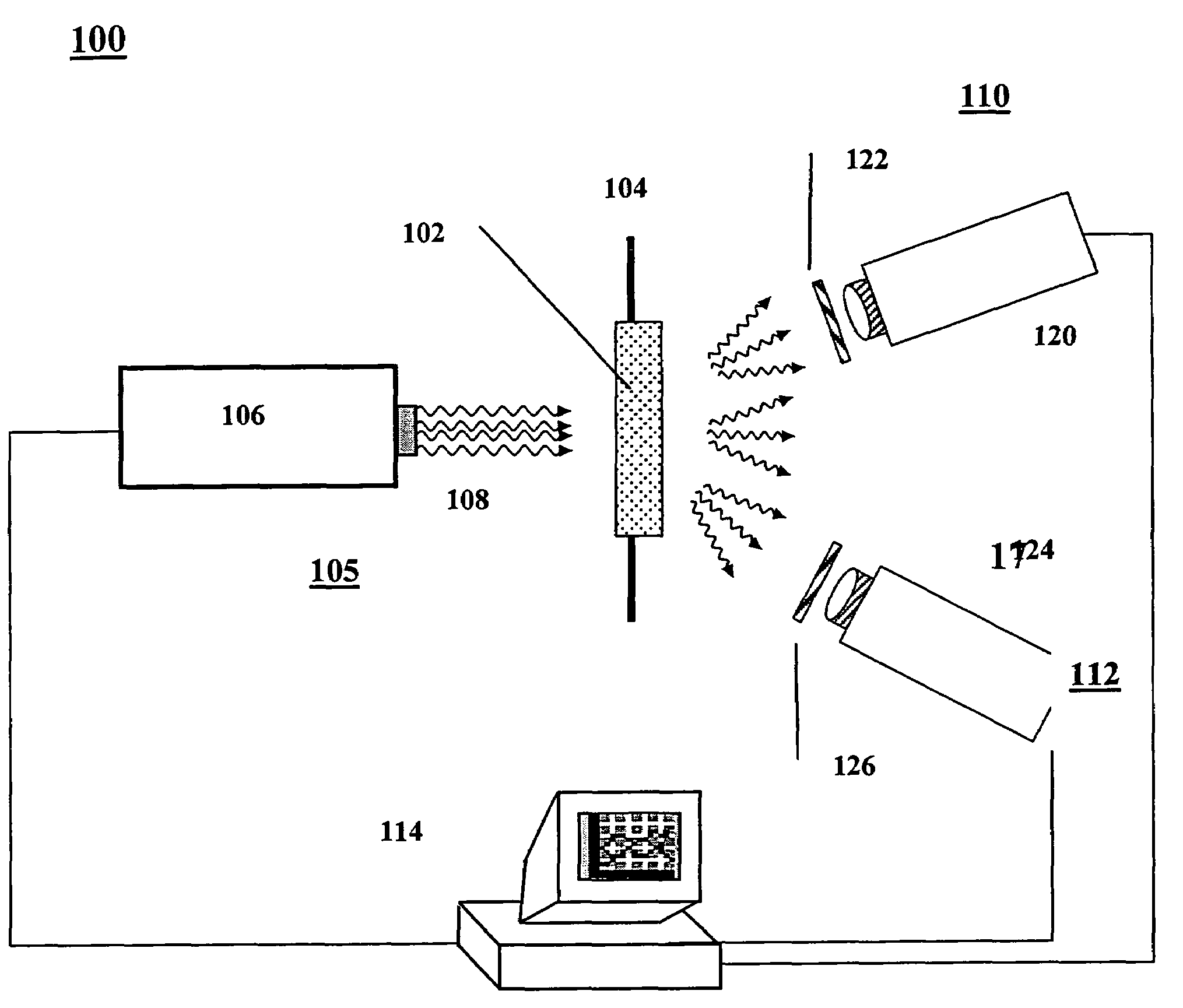
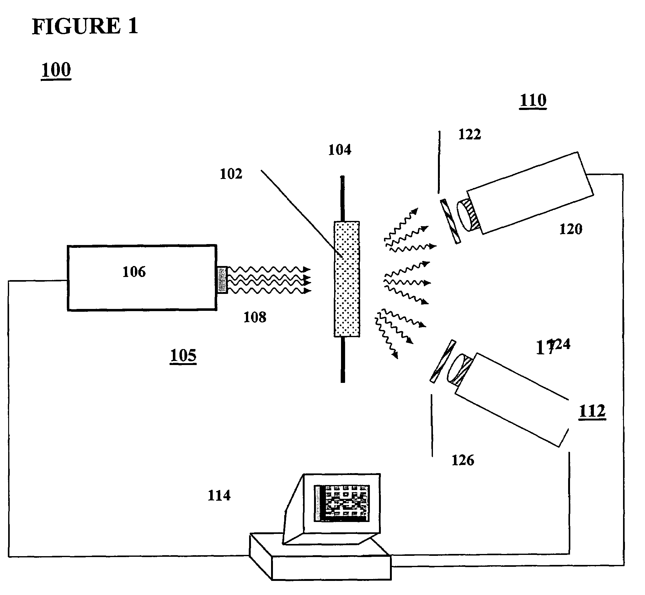
[0077]The TLD system of FIG. 3B (fiber directed radiation) was used in measurements that illustrate the applicability and performance of the method described herein. The controlled heating process in each measurement was programmed to a linear scheme from T0=30° C. to T=300° C., for three different heating periods: 15, 20, and 60 seconds. Therefore, three different heating rates were employed, from α=4.5 degrees / sec to α=18 degrees / sec. The TLD element (a standard TLD-100 3×3 mm chip manufactured by Thermo—Harshaw, Oakwood Village, Ohio, USA) was heated by a CO2 laser (Model J-48-2, Synrad, Mukilteo, Wash., USA) whose radiation (λ=10.6 μm) is highly absorbed by most materials. This mid-IR radiation cannot be transmitted through standard silica based optical fibers, but it can be easily transmitted through silver halide (e.g. AgClBr) fibers. The radiation of a CO2 laser was transmitted through one silver halide fiber to heat a spot on the surface of the TLD element. A second silver-h...


PUM


Abstract

A thermoluminescence (TL) dosimetry (TLD) system comprises at least one TLD element that is controllably heated and which temperature is monitored in real time using an infrared (IR) radiometry subsystem that provides respective IR radiation inputs to a control subsystem. The control subsystem uses the inputs to effect the heating control. The TLD system further comprises a TL measuring subsystem for measuring TL emission data from each heated TLD element, the TL data used in obtaining a does curve indicative of the total radiation to which the TLD element has been exposed.

Description

CROSS REFERENCE TO RELATED APPLICATIONS[0001]The present application claims the benefit of priority from U.S. patent application No. 60 / 606,419 filed Sep. 2, 2004, the contents of which are incorporated herein by reference.FIELD OF THE INVENTION[0002]The present invention relates generally to dosimeter systems for monitoring radiation from such radiation sources as ultraviolet, X-ray radiation, gamma radiation, beta radiation, and neutrons, and more particularly to thermoluminescence measurements and dosimetry.BACKGROUND OF THE INVENTION[0003]Radiation dosimeters, which measure the dose of incident radiation to which people, animals, plants or inanimate objects are exposed, are known. Dosimeters have been used in prior art for personal and environmental monitoring, for medical research and for radiation therapy. Of particular interest are small dosimeters, which are worn as personal badges and which need to be reliable and accurate, especially for measurements of low radiation doses...

Claims


Application Information

Patent Timeline
Patent Type & Authority Patents(United States)
IPC IPC(8): H05B33/00
CPCG01T1/11G01T1/115
Inventor KATZIR, ABRAHAMGAYER, OFER
Owner KATZIR ABRAHAM
Why Eureka
Try Eureka