
IP telephone system, IP telephone apparatus and method for identifying destination user

a telephone system and telephone system technology, applied in the field of identifying destination users, can solve problems such as the inability of the ip telephone system to specify operations

Inactive Publication Date: 2008-10-21
PANASONIC CORP
View PDF17 Cites 12 Cited by
  • Summary
  • Abstract
  • Description
  • Claims
  • Application Information

AI Technical Summary

Problems solved by technology

However, the above-described conventional IP telephone system only allows the transmitting party to specify, according to the caller's setting, an operation performed on the receiving party's end, such operations relating to the screen display or the ring tone when a call is received.
The conventional IP telephone system is not capable of specifying operations according to a call recipient's individual setting.

Method used


Image

  • IP telephone system, IP telephone apparatus and method for identifying destination user
  • IP telephone system, IP telephone apparatus and method for identifying destination user
  • IP telephone system, IP telephone apparatus and method for identifying destination user

Examples


first embodiment

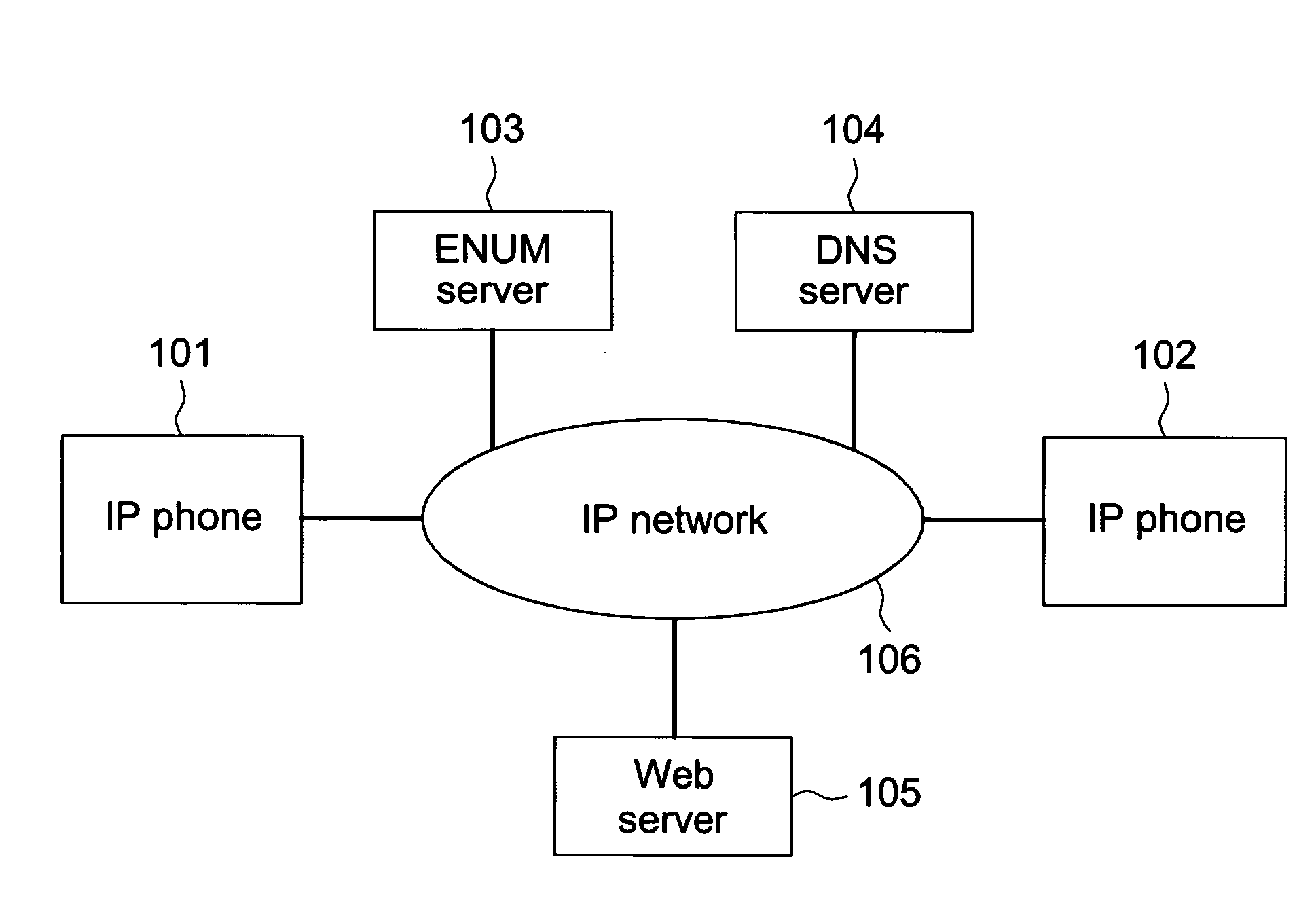
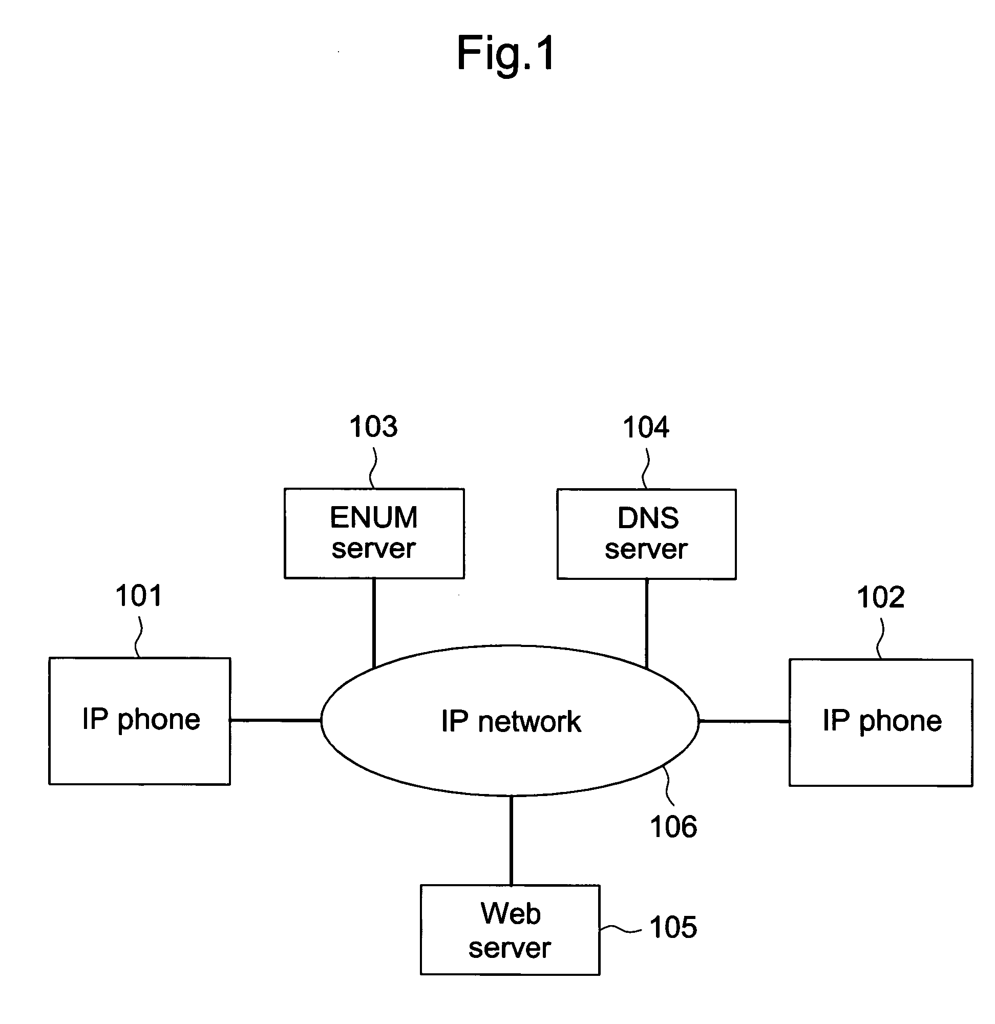
[0030]FIG. 1 illustrates a network configuration to which the IP telephone system according to the first embodiment of the present invention is applied.

[0031]As shown in FIG. 1, a plurality of IP telephone apparatuses (hereafter referred to as “IP phone”) 101 and 102, ENUM server 103, DNS server 104 and Web server 105 are mutually connected via IP network 106 in the IP telephone system according to the embodiment. Also, the IP telephone system is not limited to this embodiment and may be configured to connect three or more IP phones in IP network 106.

[0032]IP phone 101 (102) has a function enabling voice communication with another IP phone via IP network 106. IP phone 101 (102) also has a function allowing users to access Web server 105 according to the http protocol and read HTML texts provided by Web server 105.

[0033]Particularly, IP phone 102 is shared by a plurality of users. IP phone 102 also has telephone numbers assigned to each user. The following describes a case where IP p...

second embodiment

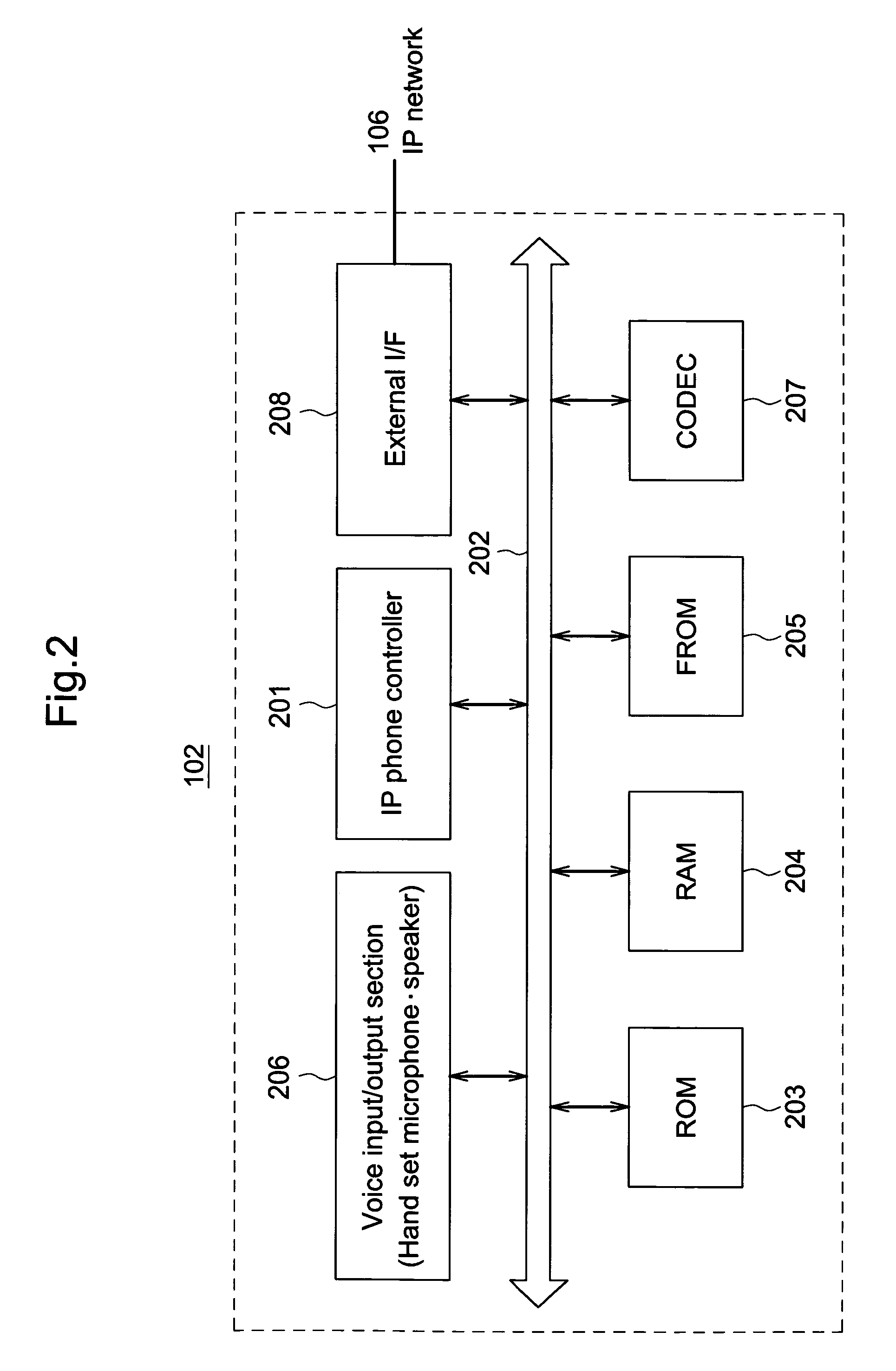
[0095]FIG. 12 is a block diagram illustrating a configuration of IP phone 102 according to the second embodiment of the present invention.

[0096]IP phone 102 shown in FIG. 12 differs from IP phone 102 in FIG. 2 in that IP phone 102 in FIG. 12 has a table, instead of FROM 205, the table storing ring tone information corresponding to each telephone number that is assigned to IP phone 102 (hereafter referred to as a “ring tone information table”). The address book data in FROM 205 is stored in the ring tone information table. Another difference is that the IP phone controller of IP phone 102 in FIG. 12 has no function to control operations related to Web server 105, but has a function which controls a ring tone according to the ring tone information stored in the ring tone information table. In FIG. 12, components identified with the same numbers as those in FIG. 2 have the same functions, and their descriptions have been omitted.

[0097]IP phone controller 1201 has the same functions as ...


PUM


Abstract

An IP telephone system includes a source IP telephone apparatus, a destination telephone apparatus, a Web server and an ENUM server. The IP telephone apparatuses are connected to an IP network. The Web server stores ring tone information corresponding to a telephone number assigned to the source or destination IP telephone apparatus. The ENUM server stores a NAPTR resource record in which a URI specifies link data related to the ring tone information stored in the Web server. In the IP telephone system, the IP telephone apparatus that has received a call transmits, to the ENUM server, a query for a NAPTR record corresponding to an intended recipient's telephone number. The IP telephone apparatus then transmits, to the Web server, a request for the ring tone information corresponding to the intended recipient's telephone number according to the obtained NAPTR resource record, and sounds a ring tone according to the obtained ring tone information

Description

BACKGROUND OF THE INVENTION[0001]1. Field of the Invention[0002]The present invention relates to an IP telephone system, an IP telephone apparatus and a method for identifying destination user.[0003]2. Description of Related Art[0004]The recent rapid growth of the Internet has drawn attention to an IP telephone system that enables low-cost voice communications with telephone apparatuses at remote places as well as free voice communications between IP telephone apparatuses owned by subscribers. Among such IP telephone systems, there is a proposal for an IP telephone system that allows the transmitting party to specify a screen display or ring tone on the receiving party's end for the purpose of improving user convenience (See Prior Art 1, for example).[0005]On the other hand, as an underlying technology, ENUM is emerging as the focus of attention, enabling communications according to individual user circumstances by effectively controlling information used for various communications ...

Claims


Application Information

Patent Timeline
Patent Type & Authority Patents(United States)
IPC IPC(8): H04L12/66H04M1/00H04M3/00
CPCH04M1/2535H04M1/26H04M3/02H04M3/42102H04M7/006H04M3/4211H04M3/42042H04M3/42017H04W4/16H04W88/18
Inventor NISHIDA, TOSHIKOTOYODA, KIYOSHI
Owner PANASONIC CORP
Learn More