
High security pin tumbler lock

a high-security, pin-type technology, applied in the direction of keyhole guards, building locks, construction, etc., can solve the problems of lock being easily “bumped” and the rotation of the plug being blocked by the projecting pins, and achieve the effect of not being easily impressioned or bumped

Active Publication Date: 2008-10-28
ACCO BRANDS USA LLC
View PDF24 Cites 12 Cited by
  • Summary
  • Abstract
  • Description
  • Claims
  • Application Information

AI Technical Summary

Benefits of technology

"The present invention provides a tubular lock that cannot be easily impressioned or bumped. The lock includes a shell containing top pins and a plug, rotatable within the shell, containing one or more standard bottom pins and a relatively shorter bottom pin, set back from the face of the plug. A tubular key has bitings corresponding to the standard bottom pins and a longer projection that corresponds to the short bottom pin. When the key is inserted in the lock, the bitings press the standard bottom pins, and the projection presses the short bottom pin, to the shear line. The key can then be turned and the lock opened. In a second exemplary embodiment, the lock includes a shell containing one or more top pins and a depression, and a plug, rotatable within the shell, containing one or more bottom pins. The depression is configured and dimensioned to receive one of the bottom pins. The bottom pins, including the one opposite the depression, are moved to the shear line when the key is inserted in the lock. The key can then be turned and the lock opened."

Problems solved by technology

However, if one or more of the top pins projects into the plug, or one or more of the bottom pins projects into the shell, rotation of the plug is blocked by the projecting pins.
However, because the smaller diameter extension of the modified bottom pin lies flush with the face of the plug, this lock can be easily “bumped.”

Method used


Image

  • High security pin tumbler lock
  • High security pin tumbler lock
  • High security pin tumbler lock

Examples


Embodiment Construction

[0021]Exemplary embodiments of the present invention will hereinafter be described in detail with reference to the accompanying drawings.

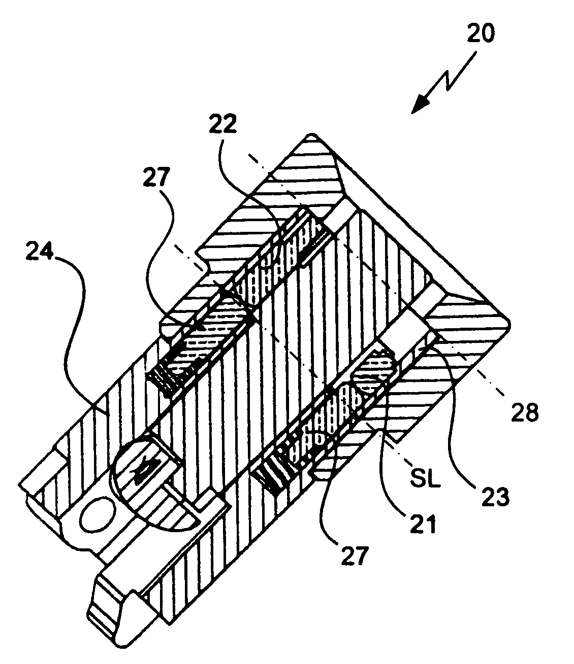
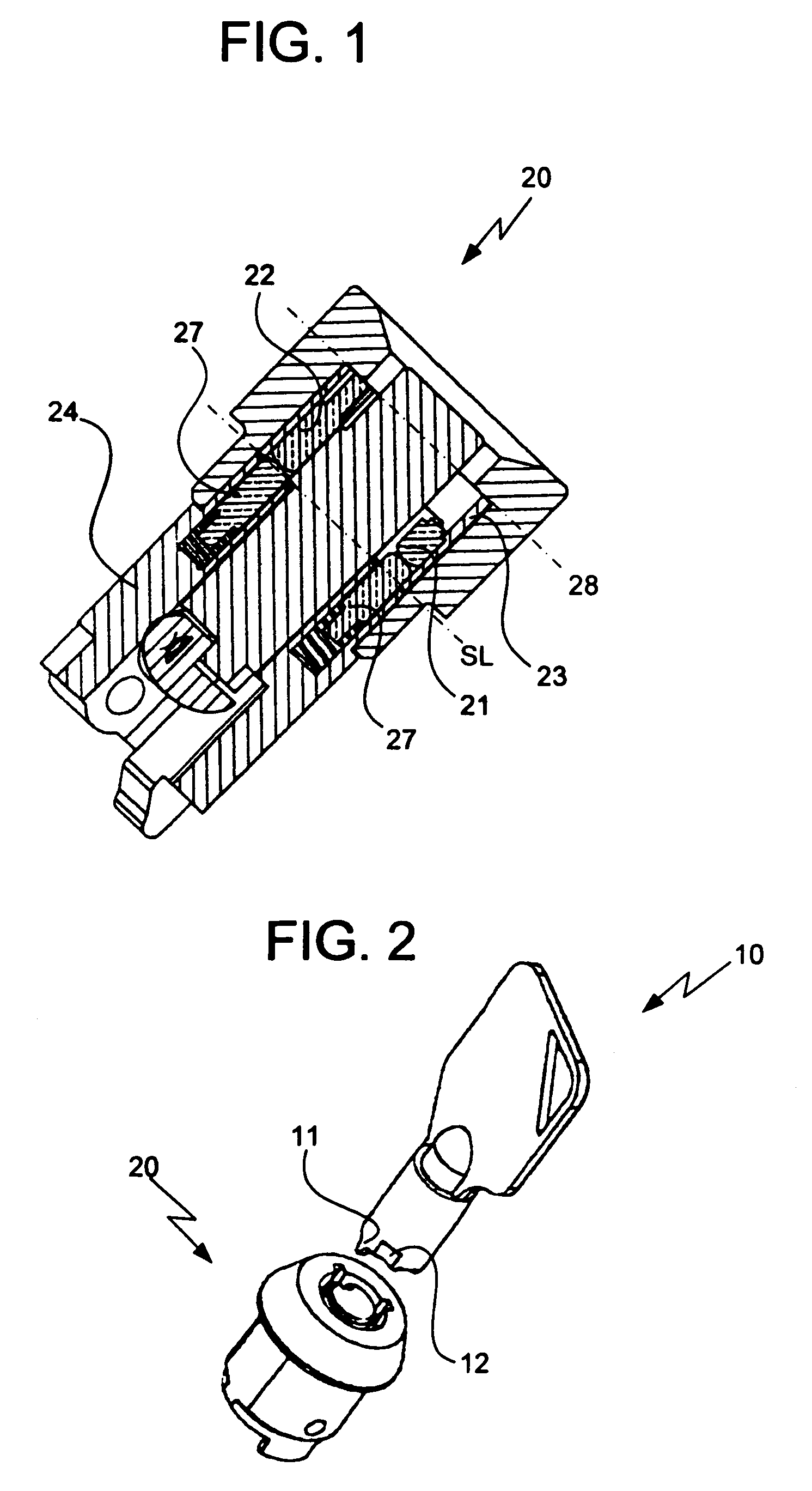
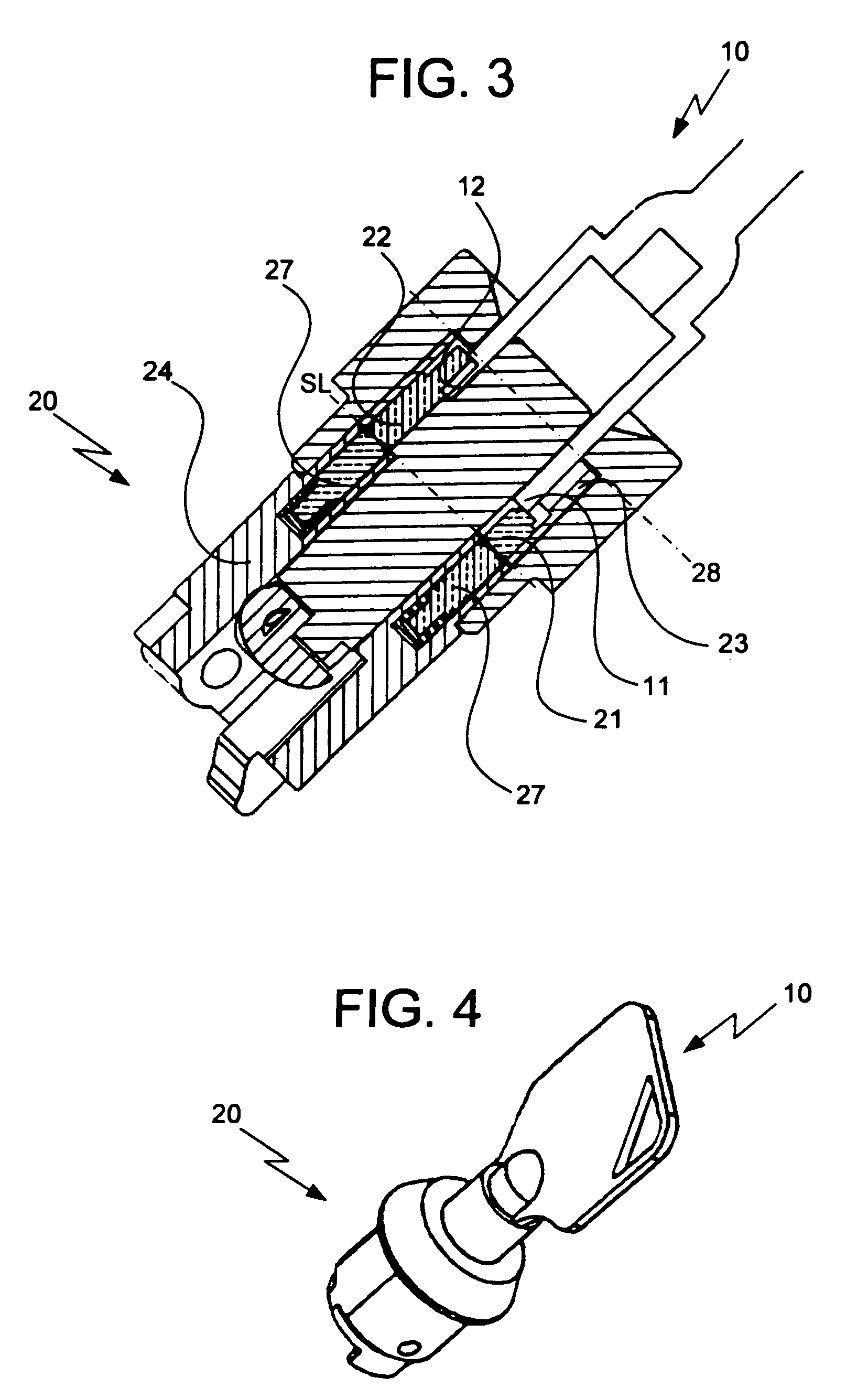
[0022]As shown in FIGS. 1-4, a first exemplary embodiment of the present invention provides a tubular key 10 comprising bitings 12 and a projection 11. Each key blank may be manufactured with the projection 11 before the bitings 12 are cut. The length of the projection 11 varies from key to key; that is, one of several possible lengths is assigned to each key 10 during manufacture. The position of the projection 11 also varies from key to key.

[0023]A lock 20 may include a shell 24 with a rotatable plug 23 disposed therein. Top pins 27 are disposed in the shell 24, each abutting a bottom pin 21, 22 disposed in the plug 23. While some of the bottom pins 22 have standard lengths, at least one bottom pin 21 is significantly shorter than the remainder of the bottom pins 22. The surface of the shortened bottom pin 21 that faces the key 10 is set back fro...


PUM


Abstract

A pin tumbler lock of a first embodiment includes a shell containing top pins; and a plug, rotatable within the shell, containing standard bottom pins, and a shorter bottom pin, set back from the face of the plug. A tubular key has bitings corresponding to the standard bottom pins, and a projection corresponding to the short bottom pin. When the key is inserted, the bitings and the projection press all the bottom pins to the shear line. In a second embodiment, a lock includes a shell containing top pins and a depression; and a plug, rotatable within the shell, containing bottom pins. The depression is configured and dimensioned to receive one of the bottom pins. The depression may be opposite one of the bottom pins, and there may be one more bottom pin than top pins. When the key is inserted, the bottom pins are moved to the shear line.

Description

CROSS-REFERENCE TO RELATED APPLICATION[0001]This application claims priority to and the benefit of U.S. Provisional Application No. 60 / 757,595, filed on Jan. 9, 2006, the entire contents of which are incorporated herein by reference.BACKGROUND OF THE INVENTION[0002](a) Field of the Invention[0003]The present invention relates to an axial pin tumbler lock, and more particularly to an axial pin tumbler lock that cannot be easily unlocked by impressioning.[0004](b) Description of the Related Art[0005]Generally, an axial pin tumbler lock, also called a tubular lock, comprises 4-7 pin tumblers located around the circumference of a circle. The body of the key is tubular and the biting corresponding to each pin tumbler is cut out of the end.[0006]A shear line lies between a rotatable plug and a fixed shell of the lock. Each biting on the key presses one bottom pin, which in turn presses a corresponding top pin. The top surface of the bottom pin and the bottom surface of the top pin are thu...

Claims


Application Information

Patent Timeline
Patent Type & Authority Patents(United States)
IPC IPC(8): E05B27/00
CPCE05B27/0057E05B27/083Y10T70/7915Y10T70/7593
Inventor WEBER, JOHN L.TOBIAS, MARC W.YU, GEORGE
Owner ACCO BRANDS USA LLC
Learn More