
Waste Processing Machine Safety Device

Active Publication Date: 2019-02-14
BANDIT IND
View PDF0 Cites 5 Cited by
  • Summary
  • Abstract
  • Description
  • Claims
  • Application Information

AI Technical Summary

Benefits of technology

The waste processing machine safety device helps improve safety by preventing objects from getting caught in the rotating disc and getting pulled towards the machine. This is done by promoting cutting, shearing, or breaking of lines, cables, and ropes.

Problems solved by technology

Those having ordinary skill in the art will appreciate that incorrect operation of waste processing machines can be potentially dangerous.
This retraction of the line, cable, or rope may be too quick for an operator to react to and may cause safety issues.
For example, retraction of the line, cable, or rope can cause the line, cable, or rope, and anything attached thereto, to be flung or whipped around, possibly causing damage or injury to nearby objects or operators.

Method used


Image

  • Waste Processing Machine Safety Device
  • Waste Processing Machine Safety Device
  • Waste Processing Machine Safety Device

Examples


Embodiment Construction

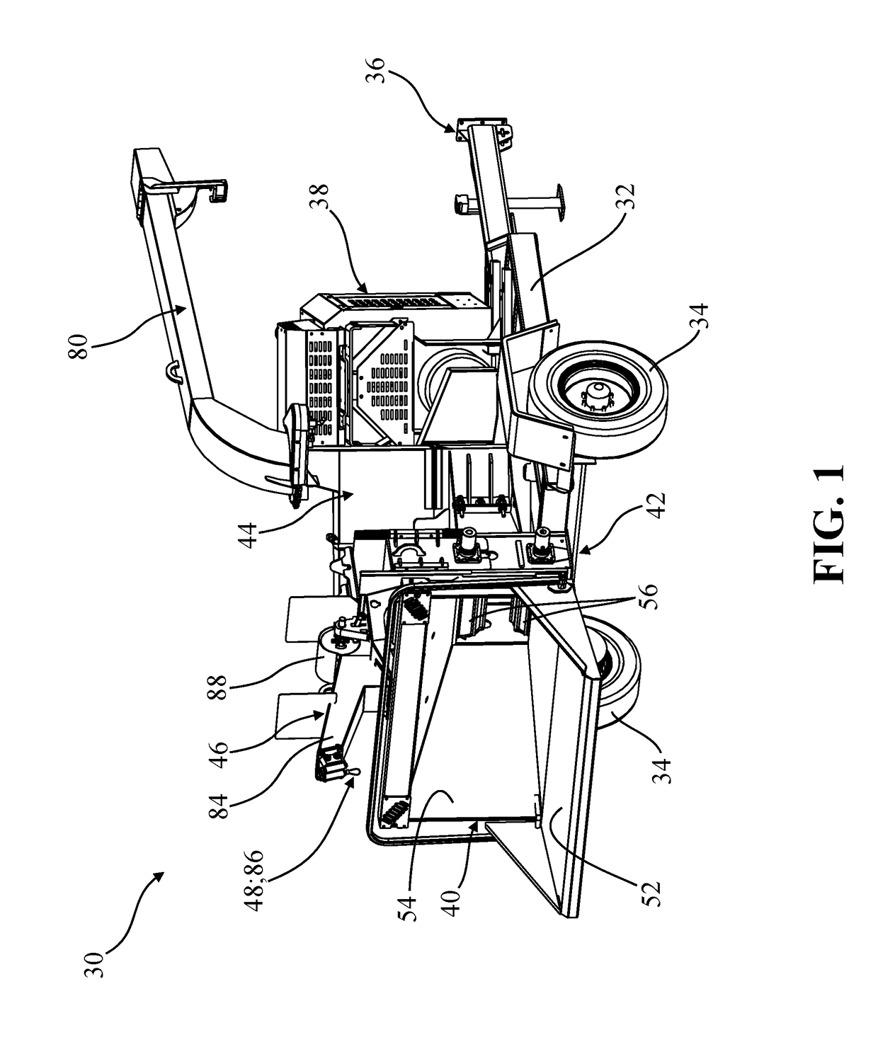
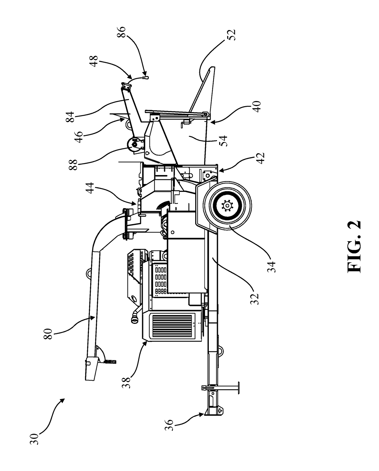
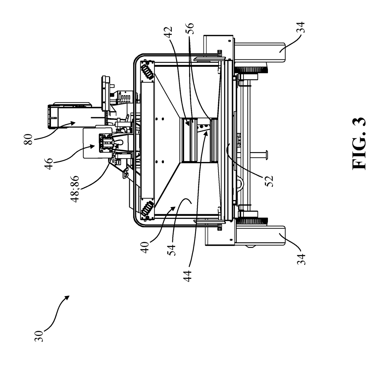
[0034]With reference to the Figures, where like numerals are used to designate like structure throughout the several views, a waste processing machine according to one embodiment of the present invention is depicted at 30 in FIG. 1. The waste processing machine 30 recycles, reduces, or otherwise processes products, such as bulk wood products, by chipping, cutting, grinding, or otherwise reducing the waste products. In the representative embodiment illustrated herein, the waste processing machine 30 is realized as a wood chipper. However, those having ordinary skill in the art will appreciate that the waste processing machine 30 could be of any suitable type or configuration sufficient to chip, grind, cut, or otherwise reduce bulk products or materials, without departing from the scope of the present invention.

[0035]Conventional waste processing machines 30, and wood chippers in particular, are regularly utilized in various industries. Those having ordinary skill in the art will appr...


PUM


Abstract

A waste processing machine for reducing waste material and having a safety device for shearing lines. A housing defines a cutting chamber and an intake opening in communication with the cutting chamber for receiving waste material. A disc is disposed in the cutting chamber, rotates about an axis, and has an axial surface facing the intake opening. A cutting member is fixed to the disc for revolution about the axis concurrent with rotation of the disc for reducing waste material. A cutting anvil is coupled to the housing adjacent to the intake opening and faces the axial surface of the disc for reducing waste material between the cutting anvil and the cutting member. A line shear element is attached to the housing, extends into the cutting chamber toward the axial surface of the disc, and is spaced from the cutting anvil for shearing lines caught by the rotating disc.

Description

CROSS-REFERENCE TO RELATED APPLICATION[0001]The subject patent application claims priority to and all the benefits of U.S. Provisional Patent Application Ser. No. 62 / 309,585 which was filed on Mar. 17, 2016 the disclosure of which is hereby incorporated by reference.BACKGROUND OF THE INVENTION1. Field of the Invention[0002]The present invention relates, generally, to waste processing machines and, more specifically, to a waste processing machine having a safety device for shearing lines.2. Description of the Related Art[0003]Conventional waste processing machines are employed to recycle, reduce, or otherwise process waste products or materials, such as bulk wood products, by chipping, cutting, grinding, or otherwise reducing the waste products. To this end, waste processing machines employ an infeed system to receive material to be reduced, such as wood products or tree limbs. A feed system with rotating feed wheels is employed to advance bulk material directed into the infeed syste...

Claims


Application Information

Patent Timeline
IPC IPC(8): B02C18/14B02C18/18B02C18/22B02C21/02B02C23/04B27G21/00B27L11/00B27L11/02
CPCB02C18/143B02C18/18B02C18/2283B02C21/02B02C23/04B27G21/00B27L11/002B27L11/02B02C2018/168B02C2018/188B27L11/00B02C18/16B02C18/06
Inventor WALCUTT, TIMOTHY RYAN
Owner BANDIT IND
Learn More