Sensor system for the control of an automatic transmission

a technology of automatic transmission and sensor system, which is applied in the direction of gearing control, mechanical equipment, transportation and packaging, etc., can solve the problems of inability to always be done away, inability to optimally diagnose the transducer, and the above-described “dynamic diagnosis” of the prior-art control device or the sensor system being described here is not yet optimal

Inactive Publication Date: 2008-10-28
ZF FRIEDRICHSHAFEN AG
View PDF10 Cites 15 Cited by
  • Summary
  • Abstract
  • Description
  • Claims
  • Application Information

AI Technical Summary

Benefits of technology

[0005]The basic object of the present invention is therefore to design and improve the prior-art sensor system of the type mentioned in the introduction such that, on the one hand, the gear limitations known hitherto are unnecessary, but, on the other hand, shifting problems that may possibly occur due to the peculiarities determined by the particular type of driver are avoided.

Problems solved by technology

In the more recent shift selector levers known according to the state of the art, this gear limitation is sometimes eliminated, especially if the transmission is designed as an automatic transmission and a “tip shifting actuation” is used.
It is problematic here at first that these first sensor elements designed as Hall position transducers cannot be optimally diagnosed at present, i.e., it is not always possible to optimally determine whether these are also able to function at a given moment, so that the corresponding gear limitation, i.e., the recesses in a shift gate which were mentioned in the introduction, cannot always be done away with for safety reasons.
On the one hand, the above-described “dynamic diagnosis” of the prior-art control device or of the sensor system being described here is not yet optimal, and, on the other hand, it is disadvantageous or problematic that the drivers of the motor vehicles tend to rest their hand on the shift selector lever while driving the motor vehicle.
This may be unfavorable from the viewpoint of safety engineering, because the control device for embodying the corresponding shifting states of the transmission which are desired by the driver in this situation no longer receives any signals any more for the “intermediate position” engaged by the shift selector lever at all, because it is not reported to the control device that the shift selector lever is engaged in position “N,” i.e., in the neutral position, or in position “R” for reverse, i.e., the control device cannot always detect the exact position of the shift selector lever at every point in time.

Method used


Image

  • Sensor system for the control of an automatic transmission
  • Sensor system for the control of an automatic transmission
  • Sensor system for the control of an automatic transmission

Examples


Embodiment Construction

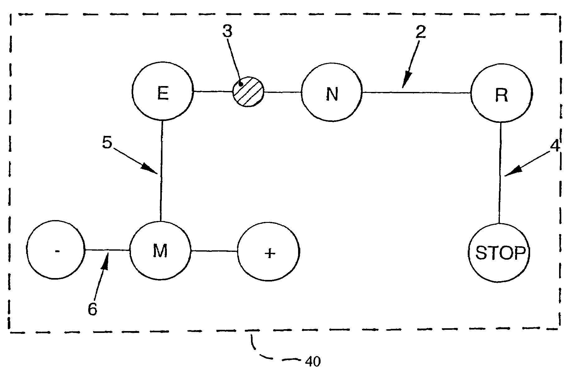
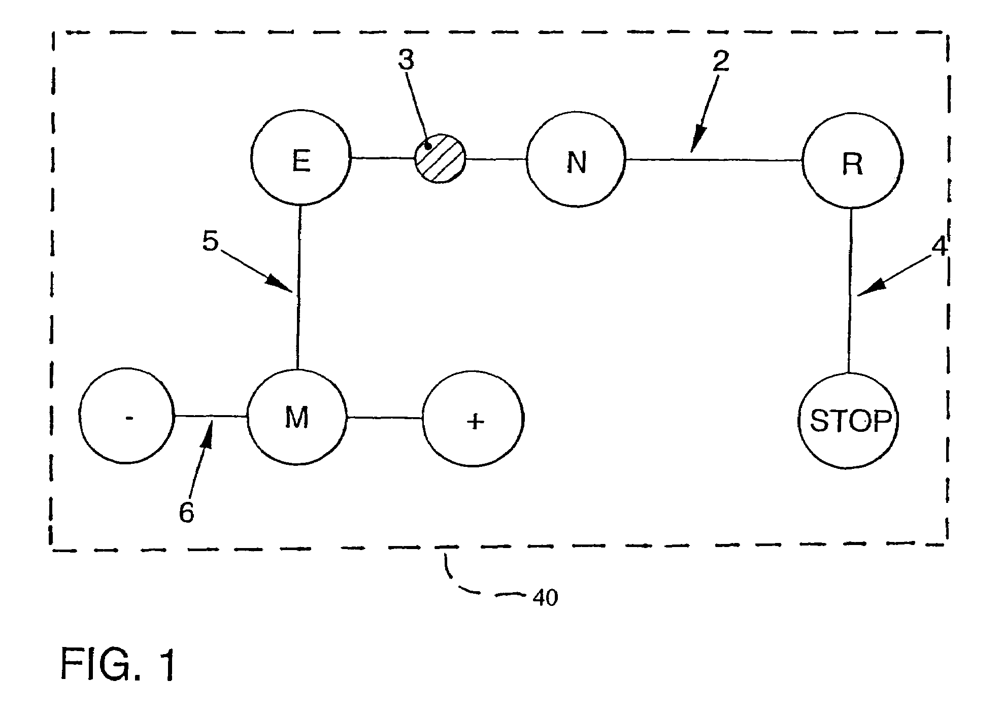
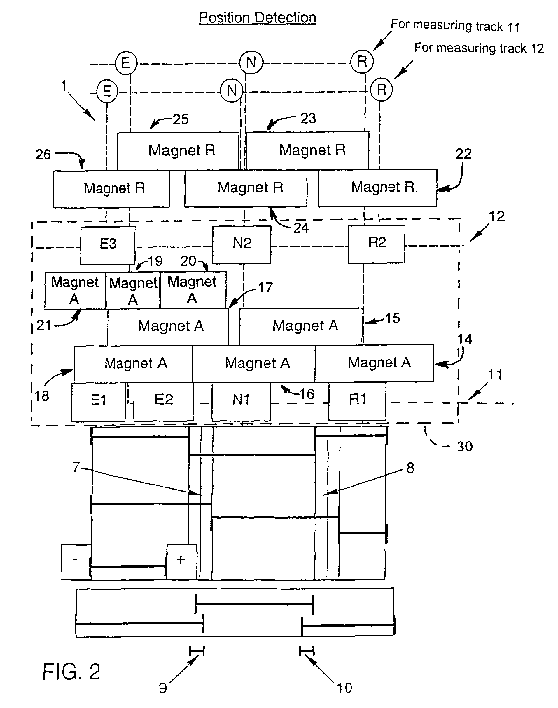
[0015]Referring to the drawings in particular, FIGS. 1 through 4 show a sensor system 1 for a control device of an automatically shiftable transmission of a motor vehicle. The control device is not shown here with all of its details. The transmission is likewise not shown here. The sensor system 1 being shown here is designed especially for an automatic manually shifted transmission. The sensor system 1 being shown may be used, in principle, in any automatically shiftable transmission of a motor vehicle. In other words, the sensor system 1 being shown here can be used for a control device that has a shift selector lever that can be moved in a single shift gate 2 only, but it can also be used in a control device where a shift gate 2, a tipping gate 6 and a transverse gate 5 are provided. This will specifically become clear below.

[0016]The control device has, in principle, at least one shift selector lever 3, which can be moved in at least one shift gate 2, as is apparent from FIG. 1....


PUM


Abstract

A sensor system is provided for a control device of an automatically shiftable transmission and/or with automatic manually shifted transmission. The system includes a shift selector lever movable in at least one shift gate for setting at least the positions Forward, Neutral, reverse, and park (stop). A position for manual shifting may also be provided for access to at least one position for the manual upshifting and/or a position for the manual downshifting of the gears of the transmission. A first sensor element is associated with each possible position. A first signal transmitter is arranged at the shift selector lever to detect the position of the shift selector lever. The first sensor elements and/or the first signal transmitter are arranged to detect a positioning of the shift selector lever at least between the positions Forward, Neutral and/or Reverse.

Description

FIELD OF THE INVENTION[0001]The present invention pertains to a sensor system for the control device of an automatically shiftable transmission, especially for an automatic manually shifted transmission, with a shift selector lever movable in at least one shift gate for setting at least the positions Forward (E), Neutral (N), Reverse (R), preferably for additionally setting a parking brake (STOP), preferably a position (M) for manual shifting, and at least one position (+) for manually upshifting and / or a position (−) for manually downshifting the gears of the transmission, wherein at least one first sensor element is associated with each possible position (E, N and R) to detect the position of the shift selector lever, and at least one signal transmitter is arranged at the shift selector lever.BACKGROUND OF THE INVENTION[0002]The shift gates known hitherto according to the state of the art have corresponding recesses for gear limitation, i.e., for setting the exact position of the ...

Claims


Application Information

Patent Timeline
Patent Type & Authority Patents(United States)
IPC IPC(8): F16H59/00B60K17/04B60K17/12F16H63/00F16H61/00B60Q1/00F16H59/02F16H59/10F16H61/12F16H61/16
CPCF16H59/0204F16H59/105Y10T74/2003F16H61/16Y10T74/19251F16H61/12
Inventor KLIEMANNEL, WOLFGANGBOSSE, ROLF
Owner ZF FRIEDRICHSHAFEN AG
Why Eureka
Try Eureka