Electrical card connector

a technology of electrical cards and connectors, applied in the direction of coupling contact members, coupling device connections, instruments, etc., can solve the problems of insufficient strength of electrical cards, easy back and forth of electrical cards, and the problem of electrical cards not being strong enough to achieve the effect of enhancing the horizontal strength of the hook

Inactive Publication Date: 2008-10-28
HON HAI PRECISION IND CO LTD
View PDF5 Cites 11 Cited by
  • Summary
  • Abstract
  • Description
  • Claims
  • Application Information

AI Technical Summary

Benefits of technology

[0007]An object, therefore, of the invention is to provide a new and improved electrical card connector of the character described able to enhance the horizontal strength of the hook to stabilize the electrical card.
[0009]As disclosed herein, the platform which defined in the opening support the planar portion so as to enhance the horizontal strength and retention between hook and insulative housing.

Problems solved by technology

Unfortunately, problems continue to be encountered with the electrical card connectors mentioned above.
When the hook is hinged or pivotally mounted on the housing, the horizontal strength for securing the electrical card is not strong enough; this makes the electrical card easy to move back and forth, i.e. unstable.

Method used


Image

  • Electrical card connector
  • Electrical card connector
  • Electrical card connector

Examples


Embodiment Construction

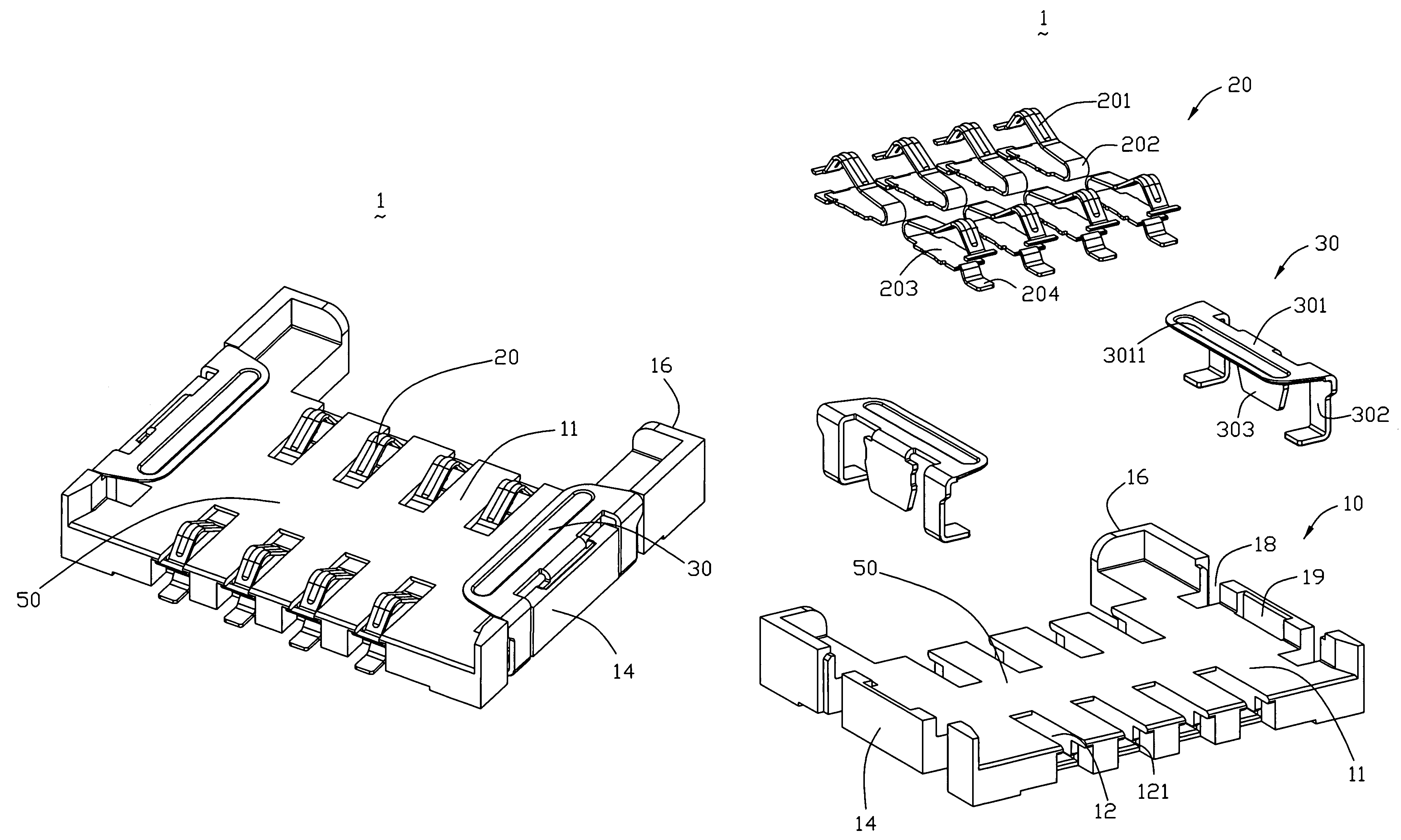
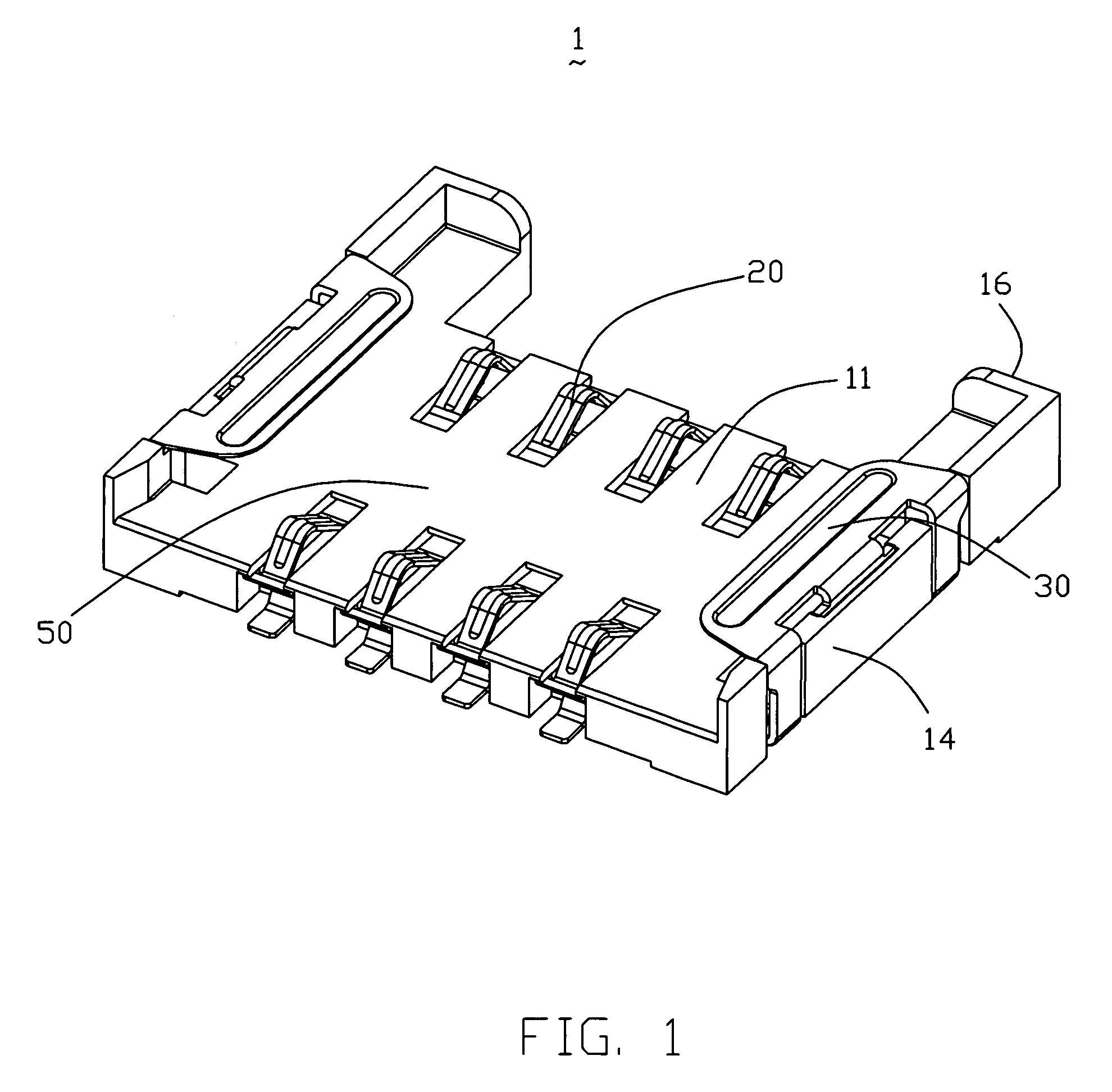
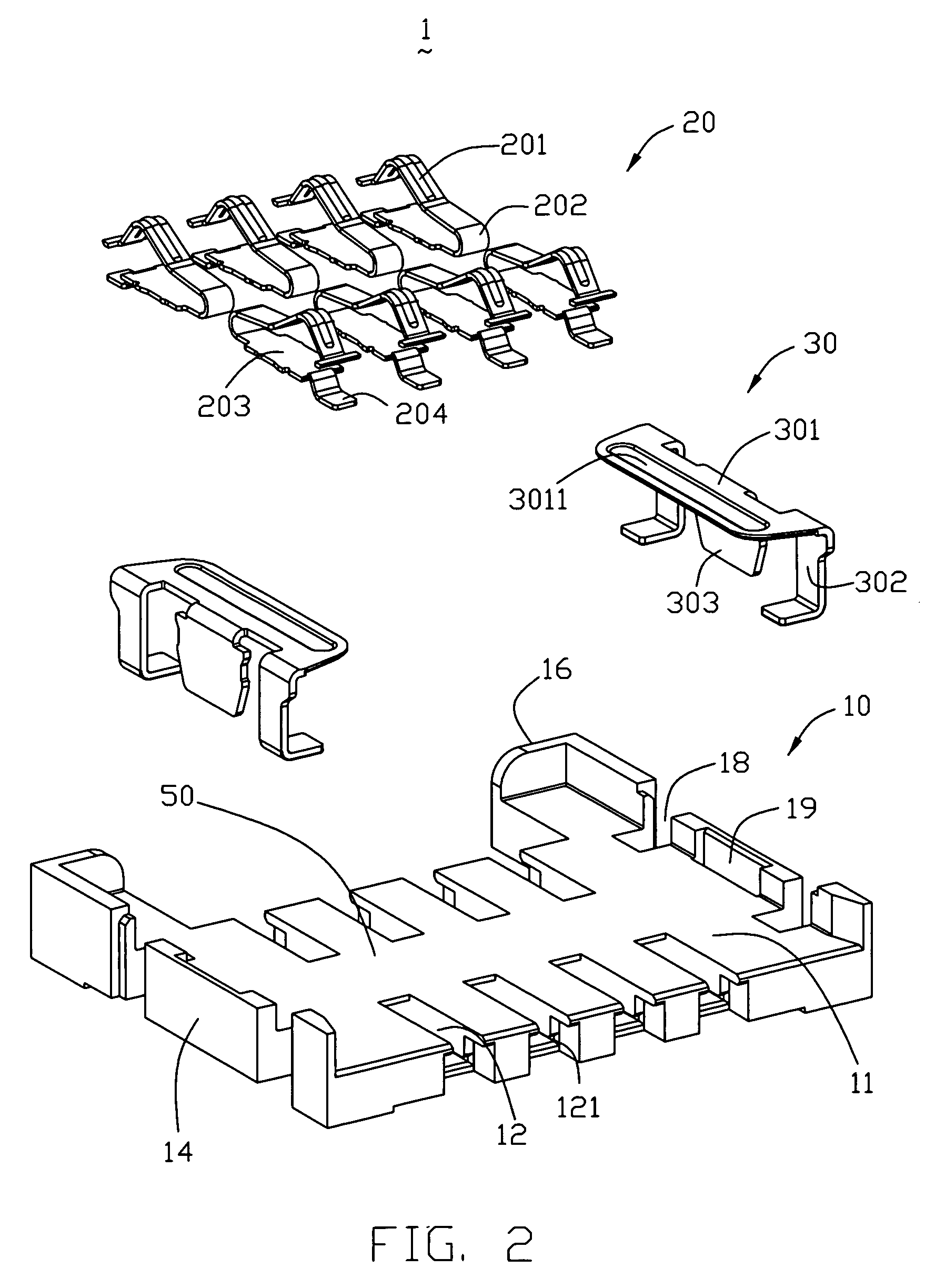
[0016]Referring to FIGS. 1-3, an electrical card connector 1 for connecting an electrical card (not shown) to a circuit board (not shown) in accordance with the preferred embodiment of the present invention comprises an insulative housing 10, a plurality of contacts 20 received in the insulative housing 10 and a pair of hooks 30 engages with the opposite sidewalls 14. The hooks 30 and the insulative housing 10 together define a receiving cavity 50 for receiving the electrical card.

[0017]The insulative housing 10 comprises a main body 11, a pair of sidewalls 14 and a rear wall 16. The main body 11 is in the form of general flat rectangular body, the sidewalls 14 and the rear wall 16 extend upwardly from three edges thereon. A plurality of passageways 12 having the slot portion 121 for receiving contacts 20 are disposed on the opposite sides of the main body 11 therein. Each sidewall 14 defines a notch portion 19 on the surface that face to the receiving cavity 50. On the two ends of ...


PUM


Abstract

An electrical card connector comprises an insulative housing 10 defining a main body 11 with a plurality of passageways 12 for receiving corresponding contacts 20 therein, the sidewalls 14 substantially parallel extend forwards from the opposite sides of the main body 11 and a rear wall 16 is also formed on the top side, a plurality of contacts 20 received in the passageways 12 and each has a contact portion 201 extending above the surface of the insulative housing 10 to contact circuitry on a card, a pair of hooks 30 engage with the insulative housing 10 defining a receiving cavity 50 together with main body 11. A pair of opening 18 runs through the opposite sidewalls 14 from the top down respectively, wherein a pair of platform 19 is defined in opening 18 for carrying the planar portion 301.

Description

BACKGROUND OF THE INVENTION[0001]1. Field of the Invention[0002]The present invention relates to card connector, especially to a card connector having a supporting platform formed with the housing so as to securely support a hook attached thereto.[0003]2. Background of the Invention[0004]Electrical cards are known in the art and contain intelligence in the form of a memory circuit or other electronic program. Some form of card reader retrieve the information or data stored on the card. Such cards are used in many applications in today's electronic society, including video cameras, digital still cameras, smart phones, PDAs, music players, ATMs, cable television decoders, toys, games, PC adapters, multi-media cards and other electronic applications, etc.[0005]Examples of prior art card-receiving connectors generally comprise a housing having connection contacts mounted thereon. The housing includes a main body which defines a plurality of passageways, a rear wall and a pair of sidewal...

Claims


Application Information

Patent Timeline
Patent Type & Authority Patents(United States)
IPC IPC(8): H01R24/00
CPCG06K7/0021G06K7/003
Inventor LONG, JI-ENKUO, WEI-NAN
Owner HON HAI PRECISION IND CO LTD
Why Eureka
Try Eureka