Optical transmission system

a transmission system and optical technology, applied in electromagnetic transmission, electromagnetic repeaters, transmission, etc., can solve the problems of inability to directly measure the cross point of input signal or output signal, inability to accurately reproduce, and difficulty in obtaining good output waveforms

Active Publication Date: 2008-10-28
FUJITSU LTD
View PDF15 Cites 9 Cited by
  • Summary
  • Abstract
  • Description
  • Claims
  • Application Information

AI Technical Summary

Benefits of technology

[0014]An object of the present invention is to make it possible that an input power to an optical nonlinear element is easily set at a value enabling to obtain a good output waveform, for any inputted optical signal.
[0016]According to the present invention, evaluation of an output signal waveform is performed by detecting a power of a specific frequency component from an electrical signal obtained by converting an optical signal reproduced by an optical nonlinear element. By making a gain of a variable amplifier increase or decrease properly based on a result thereof, an input power of an optical signal inputted to the optical nonlinear element is controlled, and thereby, the input power to the optical nonlinear element can be easily set such that a good output waveform can be obtained.

Problems solved by technology

However, if the power of the input signal deviates from the specific input power, reproduction may not be properly performed and the waveform may not be improved.
However, it is not easy to directly measure the cross point in the input signal or the output signal to determine the input power to the optical nonlinear element.
Therefore, it is difficult to respond to various input signals by a method in which the cross point is directly measured to control the input power to the optical nonlinear element to be a specific value enabling to obtain a good output waveform.

Method used


Image

  • Optical transmission system
  • Optical transmission system
  • Optical transmission system

Examples


first embodiment

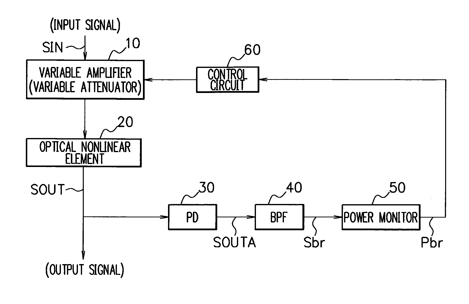
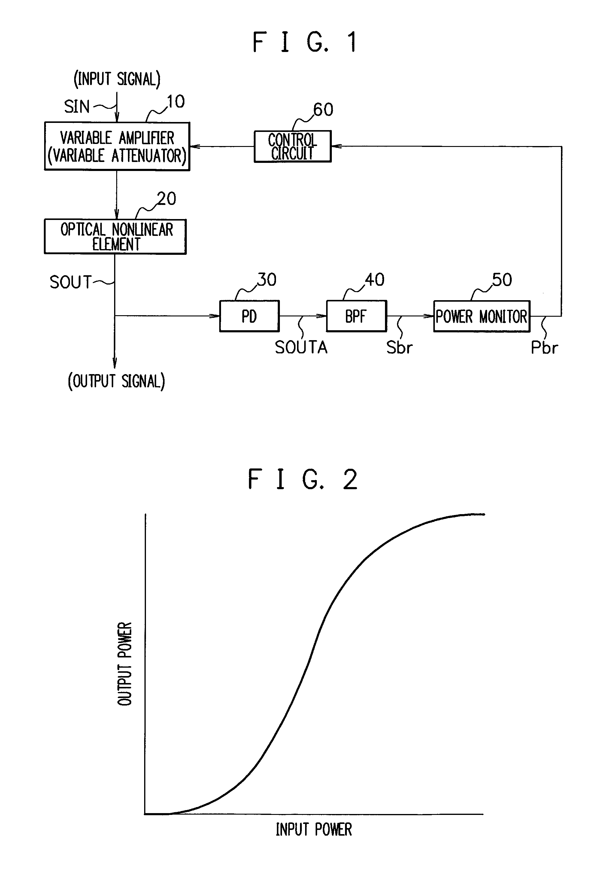
[0028]FIG. 1 is a block diagram showing a constitutional example of a reproduction interconnection device to which an optical transmission system according to a first embodiment of the present invention is applied. The reproduction interconnection device in the first embodiment shown in FIG. 1 is a reproduction interconnection device responding to an optical signal of a modulation format in which a signal level does not transit during a period equivalent to one bit, for example an NRZ (Non Return to Zero) format.

[0029]The reproduction interconnection device in the first embodiment has, as shown in FIG. 1, a variable amplifier (variable attenuator) 10, an optical nonlinear element 20, a photo detector (PD) 30, a band pass filter (BPF) 40, a power monitor 50, and a control circuit 60. The reproduction interconnection device in the first embodiment, to which an optical signal SIN is inputted as an input signal, performs reproduction thereof to output a waveform-shaped optical signal SO...

second embodiment

[0047]Next, a second embodiment of the present invention will be described.

[0048]FIG. 5 is a block diagram showing a constitutional example of a reproduction interconnection device to which an optical transmission system according to the second embodiment of the present invention is applied. In this FIG. 5, the same numerals and symbols are given to the blocks and the like having the same functions as the blocks and the like shown in FIG. 1, and the overlapping explanation will be omitted. The reproduction interconnection device in the second embodiment shown in FIG. 5 is a reproduction interconnection device responding to an optical signal of RZ (Return to Zero) format.

[0049]The reproduction interconnecting device in the second embodiment has, as shown in FIG. 5, a variable amplifier (variable attenuator) 10, an optical nonlinear element 20, a photo detector (PD) 30, a band pass filter (BPF) 41, a low pass filter (LPF) 42, power monitors 51, 52, and a control circuit 70. The reprod...


PUM


Abstract

An optical transmission system includes an optical nonlinear element having nonlinear input / output characteristics, a power detector detecting a power of a specific frequency component related to an optical signal reproduced by the optical nonlinear element, and a variable amplifier amplifying or attenuating the optical signal inputted to the optical nonlinear element. Evaluation of an output waveform is performed based on the power of the specific frequency component detected by the power detector, and a gain of the variable amplifier is properly controlled, so that an input power of the optical signal inputted to the optical nonlinear element can be easily set such that a good output waveform can be obtained without directly measuring the inputted or outputted optical signal.

Description

CROSS-REFERENCE TO RELATED APPLICATIONS[0001]This application is based upon and claims the benefit of priority from the prior Japanese Patent Application No. 2006-098288, filed on Mar. 31, 2006, the entire contents of which are incorporated herein by reference.BACKGROUND OF THE INVENTION[0002]1. Field of the Invention[0003]The present invention relates to an optical transmission system, and, in particular, is preferably used in a reproduction interconnection device in optical communication.[0004]2. Description of the Related Art[0005]In optical communication, a reproduction interconnection device is used in order to suppress deterioration of an optical signal due to a noise of an amplifier or waveform distortion during transmission. When an optical nonlinear element which has nonlinear input / output characteristics as shown in FIG. 7 is used for the reproduction interconnection device, fluctuation (noise) of level “0” and level “1” of the optical signal due to waveform deterioration ...

Claims


Application Information

Patent Timeline
Patent Type & Authority Patents(United States)
IPC IPC(8): H04B10/17H04B10/07H04B10/2507H04B10/29H04B10/293
CPCH04B10/299
Inventor AKIYAMA, TOMOYUKI
Owner FUJITSU LTD
Why Eureka
Try Eureka