Zoom lens and image pickup apparatus having the same
a pickup apparatus and zoom lens technology, applied in the direction of optics, instruments, optical elements, etc., can solve the problems of difficult to secure a sufficient peripheral light quantity, distortion tends to occur on the wide-angle side, etc., and achieve the effect of wide field angle and high optical performan
- Summary
- Abstract
- Description
- Claims
- Application Information
AI Technical Summary
Benefits of technology
Problems solved by technology
Method used
Image
Examples
numerical embodiment 1
[0101]
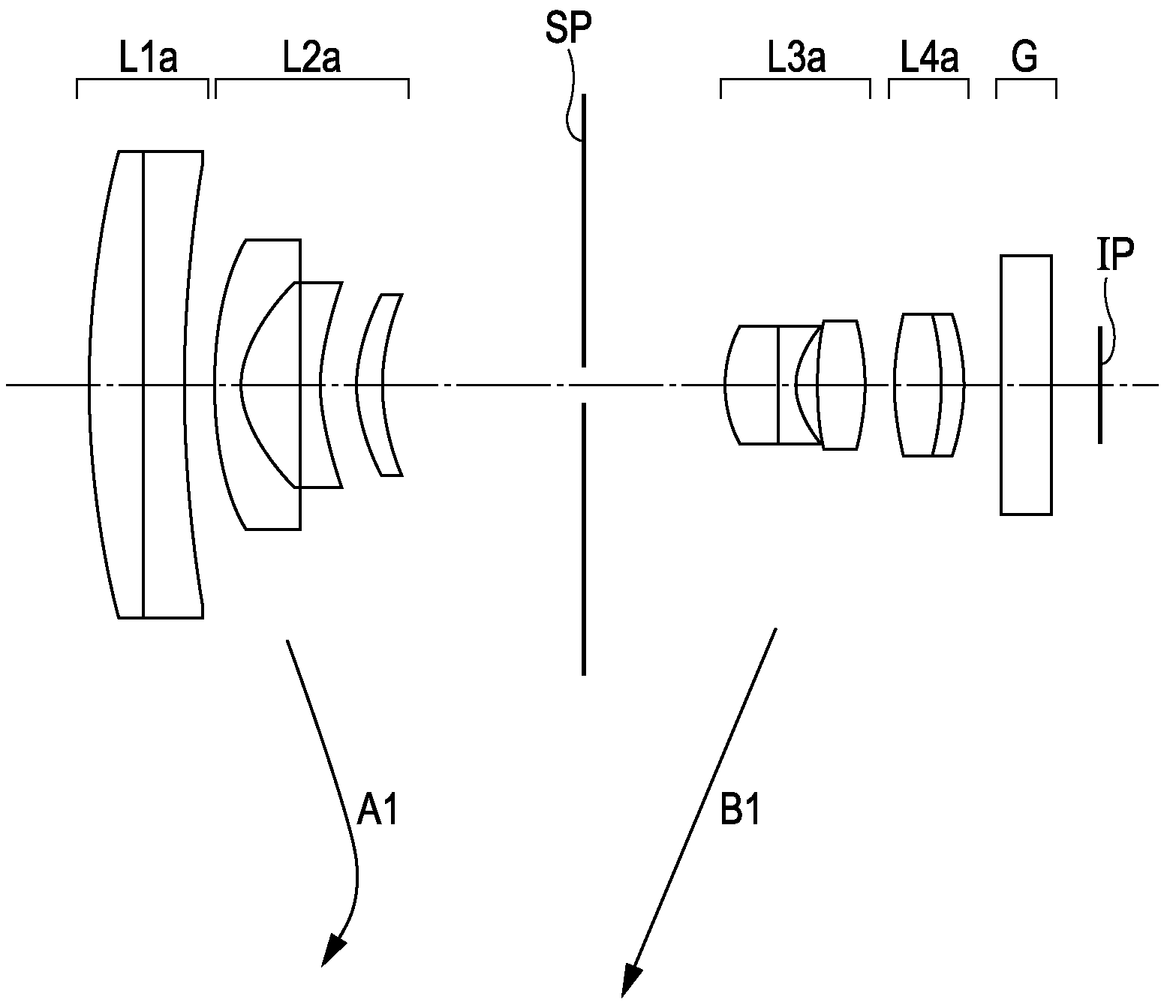
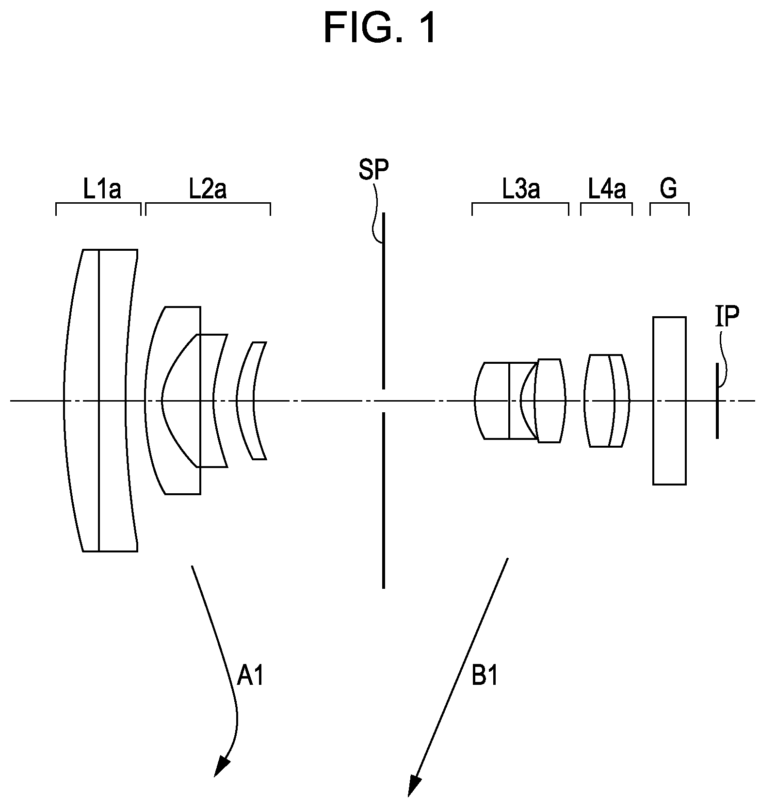
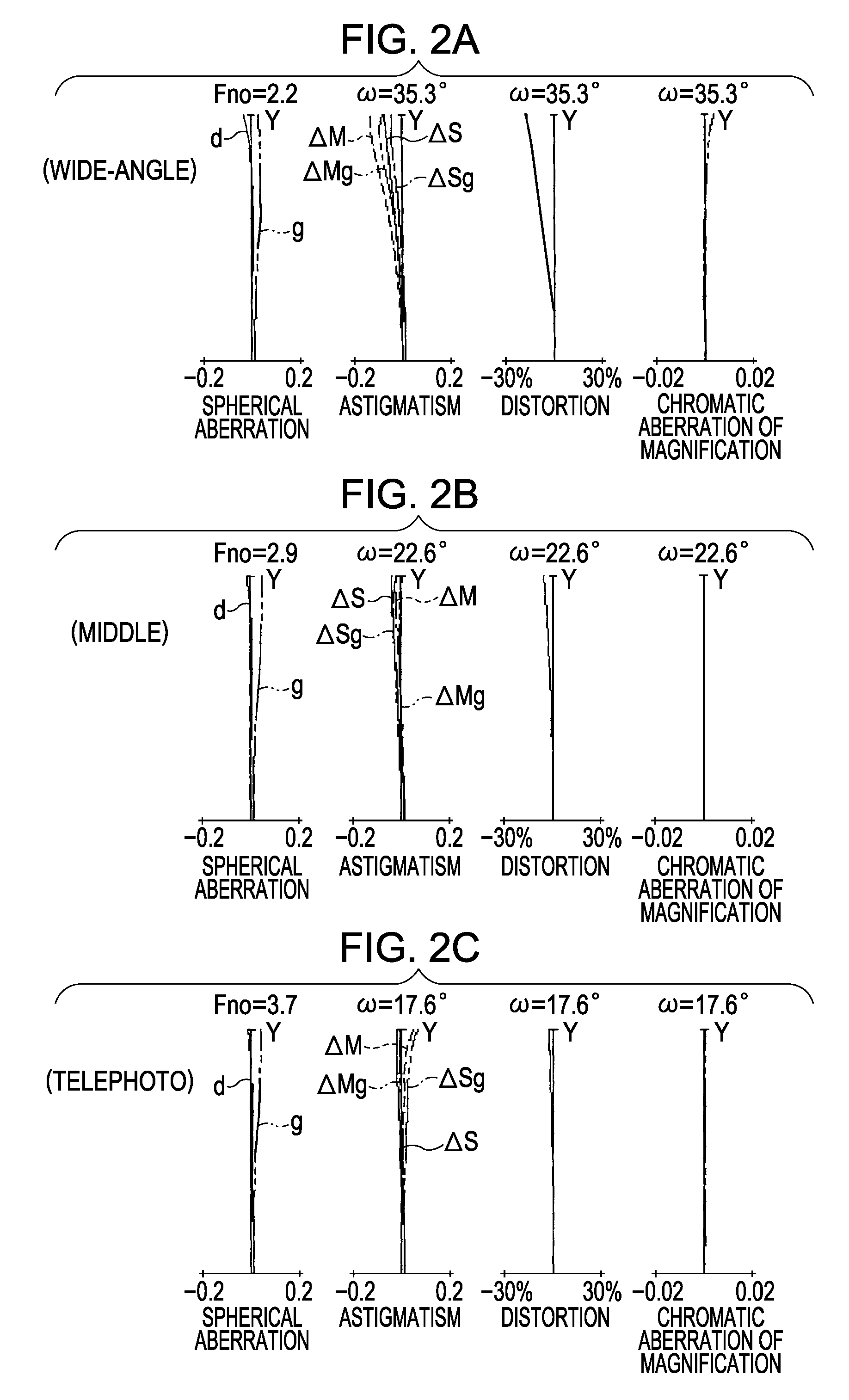
f = 3.19~5.54~7.12 Fno = 2.2~2.9~3.7 2ω = 70.4°~45.2°~35.1°R 1 = 51.878D 1 = 2.00N 1 = 1.65844ν 1 = 50.9R 2 = ∞D 2 = 1.40N 2 = 1.48749ν 2 = 70.2R 3 = 31.176D 3 = VariableR 4 = 18.957D 4 = 0.90N 3 = 1.48749ν 3 = 70.2R 5 = 5.381D 5 = 2.38R 6 = −107.116D 6 = 0.80N 4 = 1.69680ν 4 = 55.5R 7 = 9.333D 7 = 1.41R 8 = 7.695D 8 = 1.10N 5 = 1.84666ν 5 = 23.9R 9 = 11.279D 9 = VariableR10 = StopD10 = Variable*R11 = 4.661D11 = 2.00N 6 = 1.80610ν 6 = 40.7R12 = −219.325D12 = 0.80N 7 = 1.84666ν 7 = 23.8R13 = 4.469D13 = 0.70R14 = 16.348D14 = 1.80N 8 = 1.77250ν 8 = 49.6R15 = −10.230D15 = VariableR16 = 16.971D16 = 1.80N 9 = 1.51633ν 9 = 64.1R17 = −12.138D17 = 0.80N10 = 1.84666ν 9 = 23.9R18 = −19.896D18 = 1.48R19 = ∞D19 = 2.00N11 = 1.51633ν11 = 64.1R24 = ∞Focal lengthVariable distance3.195.547.12D31.506.386.59D97.752.932.66 D105.842.760.71 D151.204.286.34Aspherical coefficientsR11 k = 2.71709e−01 B = −1.17808e−03 C = −3.38618e−05D = 1.75326e−07 E = −2.10401e−07
numerical embodiment 2
[0102]
f = 3.09~5.41~7.01 Fno = 2.2~2.9~3.6 2ω = 72.1°~45.2°~35.6°R 1 = ∞D 1 = 1.00N 1 = 1.51633ν 1 = 64.1R 2 = 103.266D 2 = VariableR 3 = 44.294D 3 = 1.00N 2 = 1.48749ν 2 = 70.2R 4 = 7.020D 4 = 4.14R 5 = −17.668D 5 = 1.00N 3 = 1.60311ν 3 = 60.6R 6 = 17.688D 6 = 1.50N 4 = 1.84666ν 4 = 23.9R 7 = 101.822D 7 = VariableR 8 = StopD 8 = Variable*R 9 = 4.981D 9 = 2.00N 5 = 1.69350ν 5 = 53.2R10 = −389.300D10 = 0.80N 6 = 1.69895ν 6 = 30.1R11 = 4.641D11 = 0.70R12 = 13.524D12 = 1.80N 7 = 1.77250ν 7 = 49.6R13 = −18.660D13 = VariableR14 = 13.587D14 = 1.80N 8 = 1.83481ν 8 = 42.7R15 = −31.076D15 = 0.80N 9 = 1.84666ν 9 = 23.9R16 = 23.257D16 = 1.40R17 = ∞D17 = 2.00N10 = 1.51633ν10 = 64.1R18 = ∞Focal lengthVariable distance3.095.417.01D33.0010.6511.43D714.106.455.67D87.013.400.99 D131.004.617.02Aspherical coefficientsR 9 k = 2.44771e−01 B = −2.49699e−04 C = −2.33244e−07 D = 6.46255e−07 E = −1.04203e−07
numerical embodiment 3
[0103]
f = 3.13~5.26~7.13 Fno = 2.1~2.7~3.5 2ω = 71.4°~46.3°~35.0°R 1 = 125.000D 1 = 1.20N 1 = 1.48749ν 1 = 70.2R 2 = 32.373D 2 = VariableR 3 = ∞D 3 = 1.00N 2 = 1.48749ν 2 = 70.2R 4 = 7.207D 4 = 2.74R 5 = −179.539D 5 = 1.00N 3 = 1.48749ν 3 = 70.2R 6 = 10.494D 6 = 2.37R 7 = 9.291D 7 = 1.60N 4 = 1.76182ν 4 = 26.5R 8 = 12.367D 8 = VariableR 9 = StopD 9 = Variable*R10 = 6.237D10 = 2.50N 5 = 1.69350ν 5 = 53.2R11 = ∞D11 = 0.80N 6 = 1.69895ν 6 = 30.1R12 = 6.168D12 = 0.47R13 = 14.844D13 = 2.40N 7 = 1.60311ν 7 = 60.6R14 = −10.241D14 = VariableR15 = 52.400D15 = 2.00N 8 = 1.69680ν 8 = 55.5R16 = −8.600D16 = 0.80N 9 = 1.80518ν 9 = 25.4R17 = −32.900D17 = 1.40R18 = ∞D18 = 2.00N10 = 1.51633ν10 = 64.1R19 = ∞Focal lengthVariable distance3.135.267.13D22.6010.1510.89D811.503.953.21D97.754.151.20 D142.406.008.9Aspherical coefficientsR10 k = −6.27256e−01 B = −1.46455e−04C = −3.29397e−06 D = −6.85706e−08
PUM
 Abstract
Description
Claims
Application Information
 - R&D
- Intellectual Property
- Life Sciences
- Materials
- Tech Scout
- Unparalleled Data Quality
- Higher Quality Content
- 60% Fewer Hallucinations
Browse by: Latest US Patents, China's latest patents, Technical Efficacy Thesaurus, Application Domain, Technology Topic, Popular Technical Reports.
© 2025 PatSnap. All rights reserved.Legal|Privacy policy|Modern Slavery Act Transparency Statement|Sitemap|About US| Contact US: help@patsnap.com


