Mobile communication system, multicarrier CDMA transmitter, and multicarrier CDMA receiver

a mobile communication system and receiver technology, applied in the field of mobile communication systems, can solve problems such as frequency selective fading, interference with each other, and interference with each other by waves

Inactive Publication Date: 2008-10-28
MITSUBISHI ELECTRIC CORP
View PDF7 Cites 22 Cited by
  • Summary
  • Abstract
  • Description
  • Claims
  • Application Information

AI Technical Summary

Benefits of technology

[0029]The mobile communication system according to one aspect of the present invention, which employs a multicarrier code division multiple access, comprises a transmitting apparatus and a receiving apparatus. The transmitting apparatus has a slot generating unit that generates, for each subcarrier group unit, a slot consisting of a common pilot portion, a known series portion which the receiving apparatus uses to estimate a signal to interference ratio, and a data portion, by using transmission data converted for each subcarrier group, copies each slot by a predetermined number of subcarriers, and outputs the slots; a modulating unit that modulates the signal copied for each subcarrier unit within the sub

Problems solved by technology

As waves are reflected, diffracted, and scattered by the surrounding buildings and topography, these waves (that is, multi-path waves) arrive in the mobile communication system after passing through a plurality of transmission lines, and these waves interfere with each other (that is, frequency selective fading).
However, the above conventional mobile communication system has the following problems.
These multi-path waves interfere with each other, and the frequency selective fading, that is a random fluctuation in the amplitude and the phase of the reception wave, occurs.
Therefore, there has been a problem that it is not possible to sufficiently estimate the amplitude fluctuation and the phase fluctuation due to the fading, and the quality of the

Method used


Image

  • Mobile communication system, multicarrier CDMA transmitter, and multicarrier CDMA receiver
  • Mobile communication system, multicarrier CDMA transmitter, and multicarrier CDMA receiver
  • Mobile communication system, multicarrier CDMA transmitter, and multicarrier CDMA receiver

Examples


first embodiment

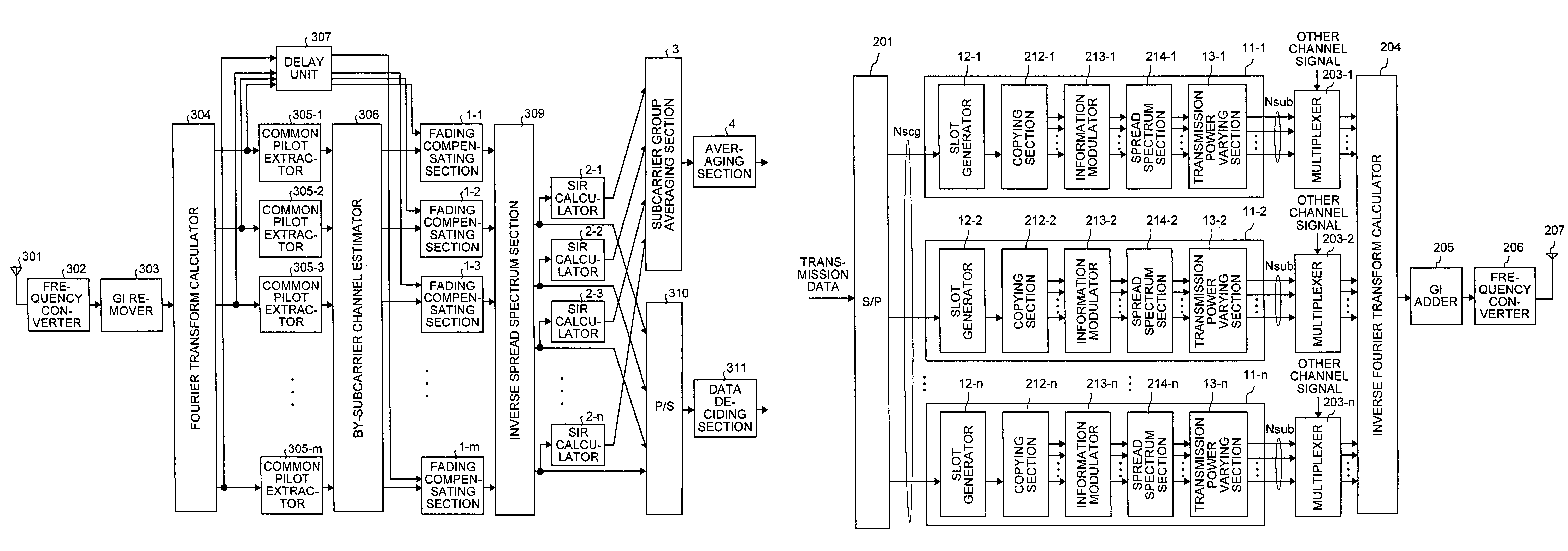
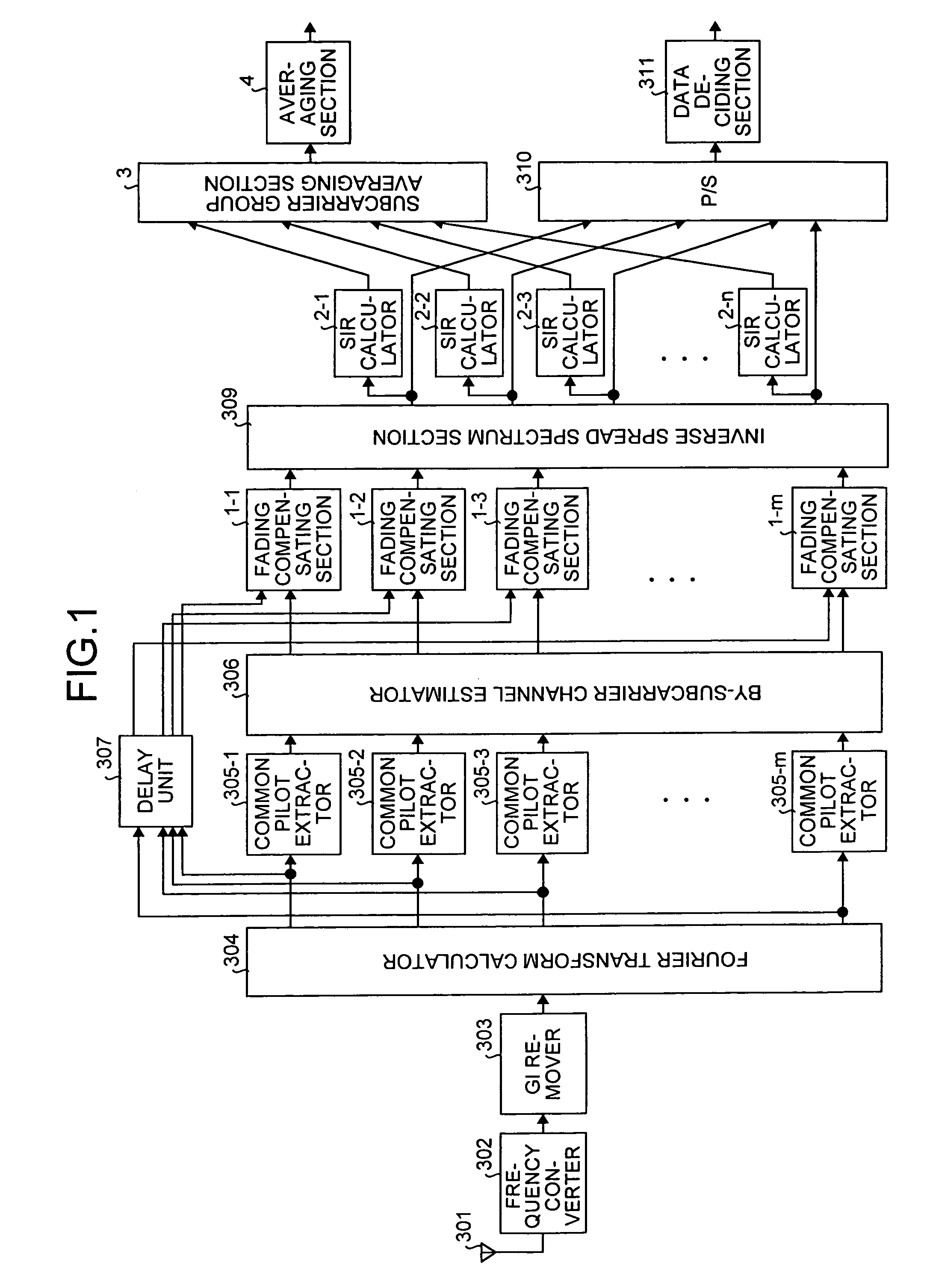
[0058]FIG. 1 shows a structure of the receiving apparatus according to a first embodiment of the present invention. In FIG. 1, the reference numeral 301 denotes the antenna, 302 denotes the frequency converter, 303 denotes the guard interval remover, 304 denotes the Fourier transform calculator, 305-1 to 305-m denote the common pilot extractors respectively, 306 denotes the by-subcarrier channel estimator, 307 denotes the delay unit, 1-1, 1-2, 1-3, . . . , and 1-m denote fading compensating sections respectively, 309 denotes the inverse spread spectrum section, 2-1, 2-2, 2-3, . . . , and 2-n denote SIR calculators, 310 denotes the parallel to serial converter, 311 denotes the data deciding section, 3 denotes a subcarrier group averaging section, and 4 denotes an averaging section.

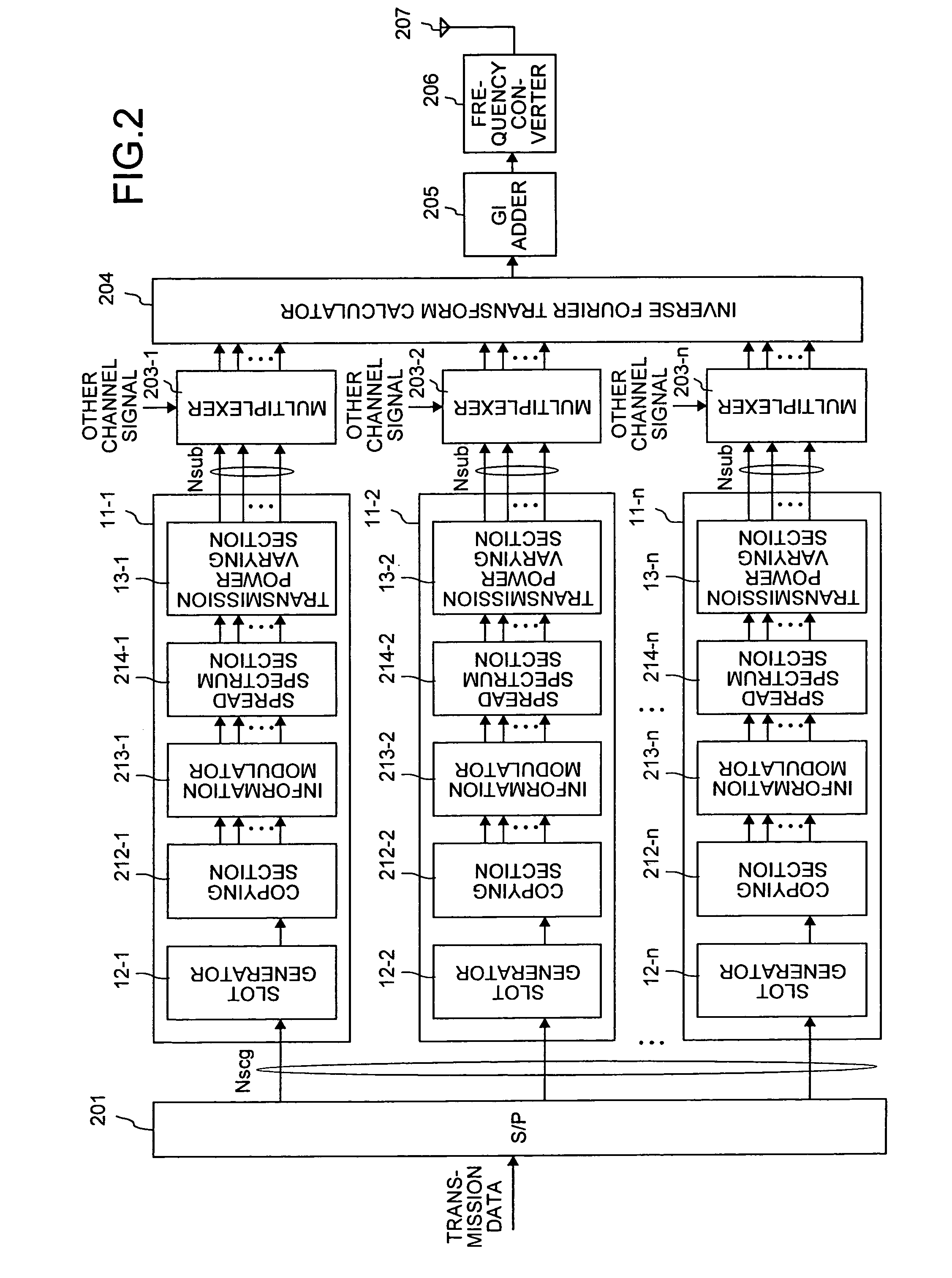
[0059]FIG. 2 shows a structure of the transmitting apparatus according to the first embodiment. In FIG. 2, the reference numeral 201 denotes the serial to parallel converter (S / P), 11-1, 11-2, . . . , and 1...

second embodiment

[0095]In the mobile communication system according to a second embodiment, the SIR calculating method of the SIR calculator within the receiving apparatus is different from the SIR calculating method according to the first embodiment. Only the portions that operate differently from those in the first embodiment will be explained below. The transmitting apparatus and the receiving apparatus according to the second embodiment have similar structures to those shown in FIG. 1 and FIG. 2 respectively.

[0096]FIG. 10 shows a structure of SIR calculator according to the second embodiment. A reference numeral 61 denotes an averaging section. The averaging section 61 is input with average interference power for each slot output from the averaging section 59. The averaging section 61 further averages the average interference power by using a plurality of slots. The structure of the averaging section 61 is the same as that shown in FIG. 8 or FIG. 9.

[0097]Even in the present embodiment, it is pos...

third embodiment

[0101]In the mobile communication system according to a third embodiment, the operation of an information modulator within the transmitting apparatus is different from that according to the first or the second embodiment. Only the portions that operate differently from those in the first or the second embodiments will be explained below. The transmitting apparatus and the receiving apparatus according to the third embodiment have similar structures to those shown in FIG. 1 and FIG. 2 respectively.

[0102]FIG. 11 shows a structure of the information modulator according to the third embodiment. Reference numerals 81-1, 81-2, . . . , and 81-m denote multi-value modulators. Each information modulator receives Nsub subcarrier signals. Then, the multi-value modulators 81-1, 81-2, . . . , and 81-m multi-value modulate these signals, and generate Nsub subcarrier signals after the information modulation. The multi-value modulation includes modulation systems that make it possible to transmit a...


PUM


Abstract

A transmitting apparatus adds a common pilot symbol and known series for each data slot of a subcarrier group. A receiving apparatus combines SIR calculation values obtained for each subcarrier group, and averages the SIR calculation values. Based on this, it is possible to obtain a high-precision SIR calculation value even when there is a level fluctuation such as shadowing.

Description

TECHNICAL FIELD[0001]The present invention relates to a mobile communication system that employs a multicarrier CDMA, a multicarrier CDMA transmitting apparatus (hereinafter, “transmitting apparatus”), and a multicarrier CDMA (Code Division Multiple Access) receiving apparatus (hereinafter, “receiving apparatus”). The present invention relates, more particularly, to a transmitting apparatus and a receiving apparatus that are used in a frequency selective fading transmission line.BACKGROUND ART[0002]A conventional mobile communication system that employs a multicarrier CDMA is explained below. Transmitting and receiving apparatuses of a mobile communication system according to a multiple access system using a multicarrier CDMA system are described in, for example, “Comparison of characteristics between the SC (Single Carrier) / DS (Direct Spread)-CDMA, MC (Multi Carrier) / DS-CDMA, and MC-CDMA systems in the down link broadband radio packet transmission, The Institute of Electronics, Inf...

Claims


Application Information

Patent Timeline
IPC IPC(8): H04B7/216H04B1/02H04B1/06H04L27/00H04B1/707H04B7/26H04J1/00H04J11/00H04J13/00H04L1/20H04L5/02H04L25/02H04L27/26H04W28/18H04W52/04
CPCH04L1/20H04L5/026H04L25/0232H04L27/2647
Inventor SANO, HIROYASU
Owner MITSUBISHI ELECTRIC CORP
Why Eureka
Try Eureka