
Vending machine

a vending machine and machine body technology, applied in the field of vending machines, can solve the problems of poor reliability, difficult to increase the storage capacity of the machine, and difficult to efficiently match product demand with storage capacity, and achieve the effect of enhancing the sales of primary products

Inactive Publication Date: 2008-10-28
CHIRNOMAS MUNROE
View PDF5 Cites 13 Cited by
  • Summary
  • Abstract
  • Description
  • Claims
  • Application Information

AI Technical Summary

Benefits of technology

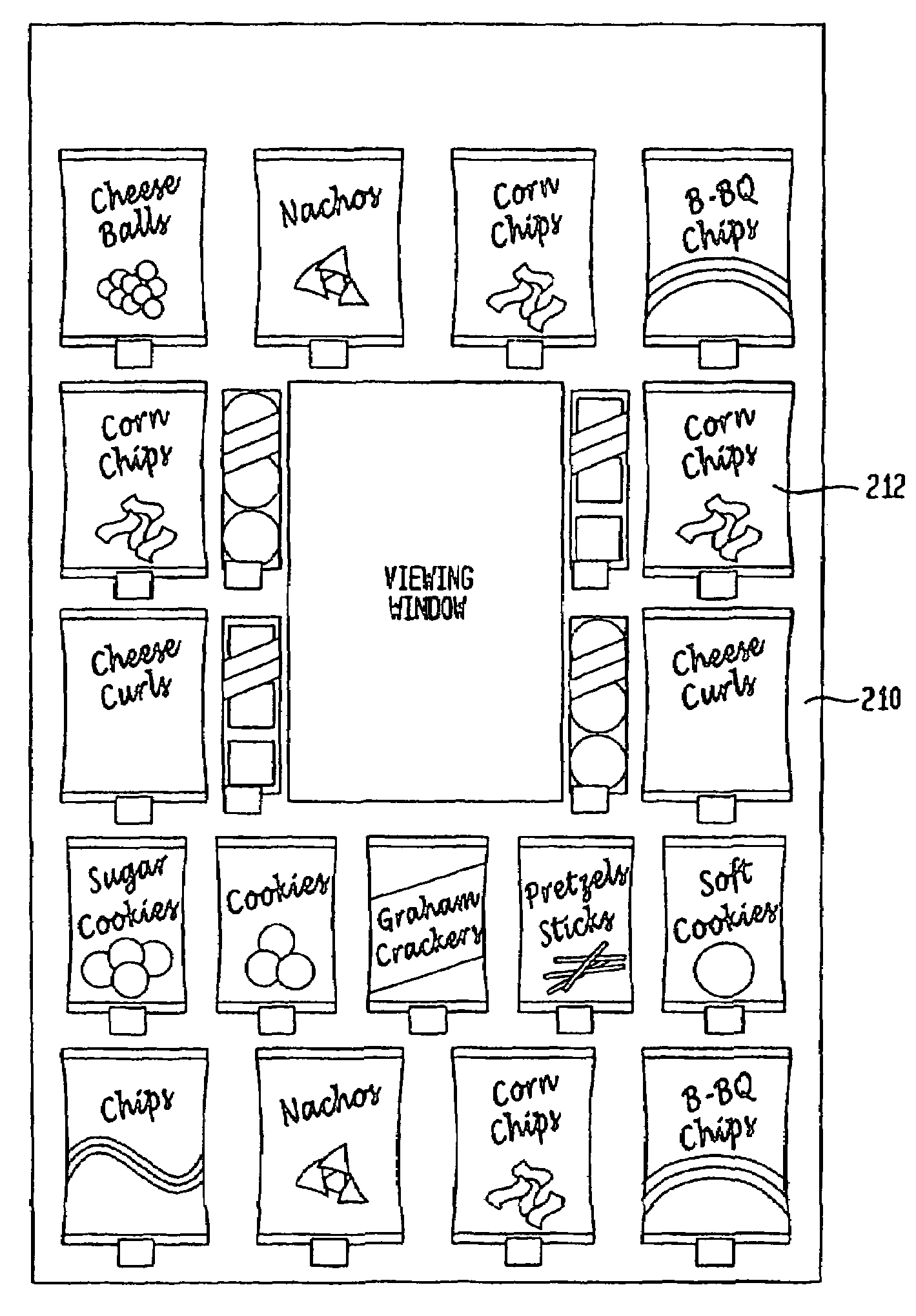
[0010]In accordance with one aspect of the invention, product display panels are provided in conjunction with a vending machine which enhance the sales of primary products as compared with secondary products also vendible therefrom.
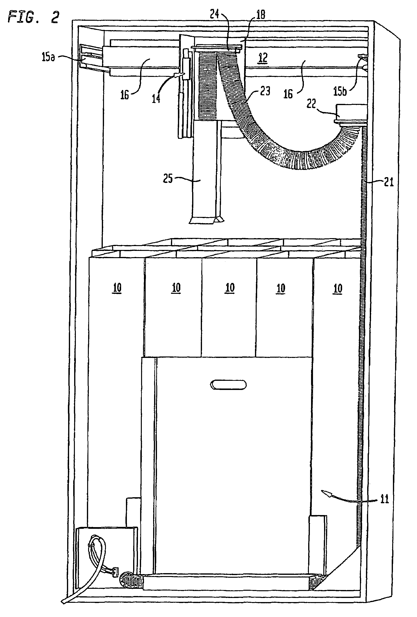
[0011]In accordance with further aspects of the invention, a rotational coupling is added to a vacuum hose in the product lifting mechanism of the vending machine, to improve the fit of vacuum hose to the product during lifting and dispensing operations, thereby enhancing its ability to transport unbalanced products, as well as decrease the forces, caused by rotation of the vacuum hose, between the product and the product containment wall, thereby reducing the chance of dropping the product. Further improvements relating to the product lifting mechanism are also shown in the Figures which follow, such as an additional rotational coupling in a cable of the lifting mechanism to compensate for rotation of the vacuum hose during its extension or contraction. An alternate embodiment can utilize the addition of a stabilizer ring or suction cup at the lifting product lifter head for improving the stability and grasp of larger product, especially of the air-filled type (such as potato chip bags).
[0012]In accordance with other aspects of the invention, improvements are provided to the product storage container system, as well as a coordination of these improvements with the structure of the vending machine cabinet, so as to increase product storage capacity, as well as improve the ease and efficiency of product handling, access and loading of product into the machine, in a cost effective and reliable manner while still retaining the structural rigidity and integrity of the cabinet.

Problems solved by technology

Such machines generally suffer from numerous disadvantages, such as poor reliability due to mechanical failures, as well known to those skilled in this art.
This conventional arrangement suffers from several disadvantages: each piece of each product must be separately handled to load the machine, once the machine is in the field there is little flexibility to change the number or types of columns, it is difficult to efficiently match product demand with storage capacity, and it is difficult to increase the storage capacity of the machine.
This can be an undesirable situation, since sometimes a product supplier or manufacturer provides financial assistance to a machine operator of a vending machine with the expectation that product purchases for that machine will compensate the product supplier for the financial assistance.

Method used


Image

  • Vending machine
  • Vending machine
  • Vending machine

Examples


Embodiment Construction

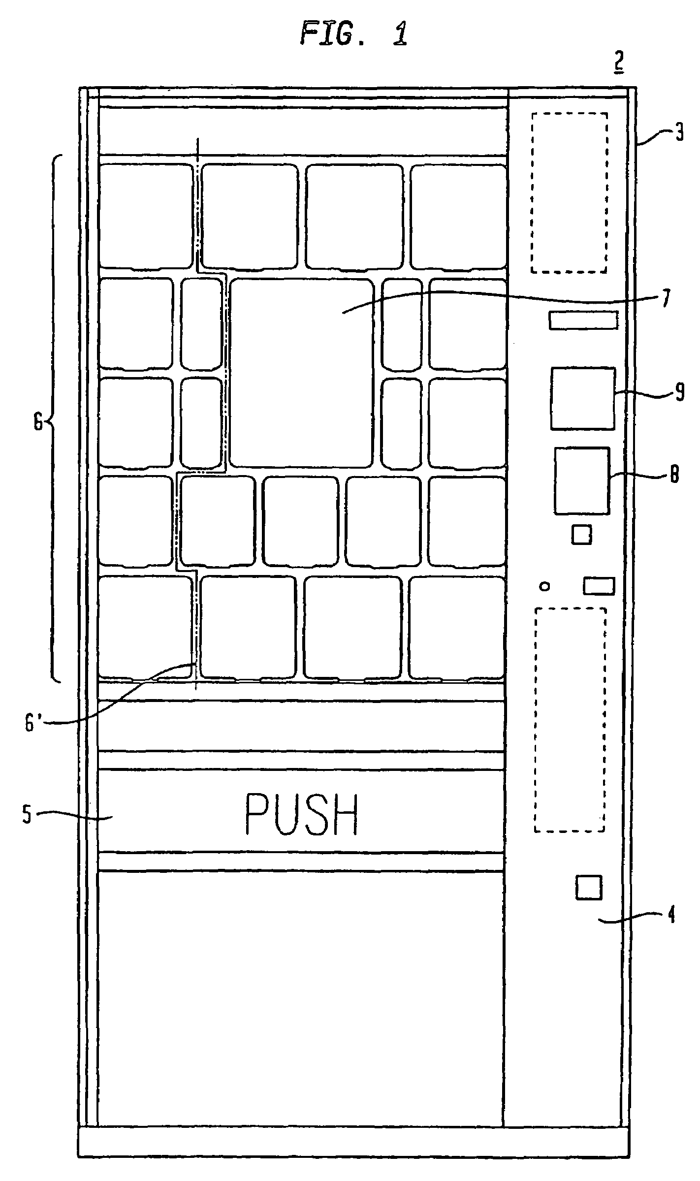
[0031]FIG. 1 shows a vending machine 2 having a generally rectangular 3-dimensional outer housing (cabinet) 3 including a front loading door 4. (Note, in an alternative embodiment a loading door or port could be positioned anywhere on the cabinet.) A customer retrieval door 5 is disposed in a lower part of door 4 while the upper part of door 4 is dominated by a lighted product display area 6. Product display area 6, as described in detail later on, includes a plurality of graphic display panels which illustrate the individual products that are vendible by machine 2, as well as the price and / or selection information for the respective product. A line 6′ illustrates a division in display area 6, where all of the individual product graphics which are, for example to the left side of line 6′, are on individual panels or display cards, while all of the individual product graphics which are to the right side of line 6′ are comprised of multiple graphics for multiple product Selections whi...


PUM


Abstract

The present invention relates generally to improvements in article handling, such as in vending machines, and more particularly, to improvements in:methods and apparatus for handling articles using a vacuum-type product lifting / dispensing mechanism,article display panels which enhance sales of primary products, andproduct containment systems which improve product storage capacity, as well as the ease and efficiency of product handling, access and loading into the article handling apparatus.

Description

CROSS-REFERENCE TO RELATED APPLICATIONS[0001]This application is a continuation of and claims priority under 35 USC 120 of prior U.S. Ser. No. 10 / 306,807, filed Nov. 27, 2002, now U.S. Pat. No. 7,044,330 entitled VENDING MACHINE, which prior application claims priority under 35 USC 120 of U.S. Ser. No. 09 / 633,477, filed Aug. 7, 2000, entitled VENDING MACHINE, which itself claims priority under 35 USC 120 of U.S. Provisional Patent Application No. 60 / 147,832, filed Aug. 7, 1999, entitled VENDING MACHINE. The entire disclosure of each of the above patent applications are incorporated herein by reference in their entirety.BACKGROUND OF THE INVENTION[0002]1. Field of the Invention[0003]The present invention relates generally to improvements in vending machines. More particularly, the present inventions relate to improvements in apparatus for dispensing of product using a vacuum-type product lifting / dispensing mechanism, in product display panels which enhance sales of primary products, ...

Claims


Application Information

Patent Timeline
Patent Type & Authority Patents(United States)
IPC IPC(8): G06F17/00
CPCG07F9/02G07F11/14G07F11/165G07F11/1657
Inventor CHIRNOMAS, MUNROE
Owner CHIRNOMAS MUNROE
Learn More