Low lethality projectile

a projectile and low lethality technology, applied in the field of projectiles, can solve the problems of inflicting serious injury and not being able to impact the projectile, and achieve the effect of low lethality

Inactive Publication Date: 2008-11-04
COMBINED SYST
View PDF27 Cites 14 Cited by
  • Summary
  • Abstract
  • Description
  • Claims
  • Application Information

AI Technical Summary

Benefits of technology

[0009]More particularly, it is an object to impose a low

Problems solved by technology

The shape of the above described projectile at impact is not always predictable based solely on its construction as a bag, because the bag can be flat at impact only if it unfolds after exiting from th

Method used


Image

  • Low lethality projectile
  • Low lethality projectile

Examples


Embodiment Construction

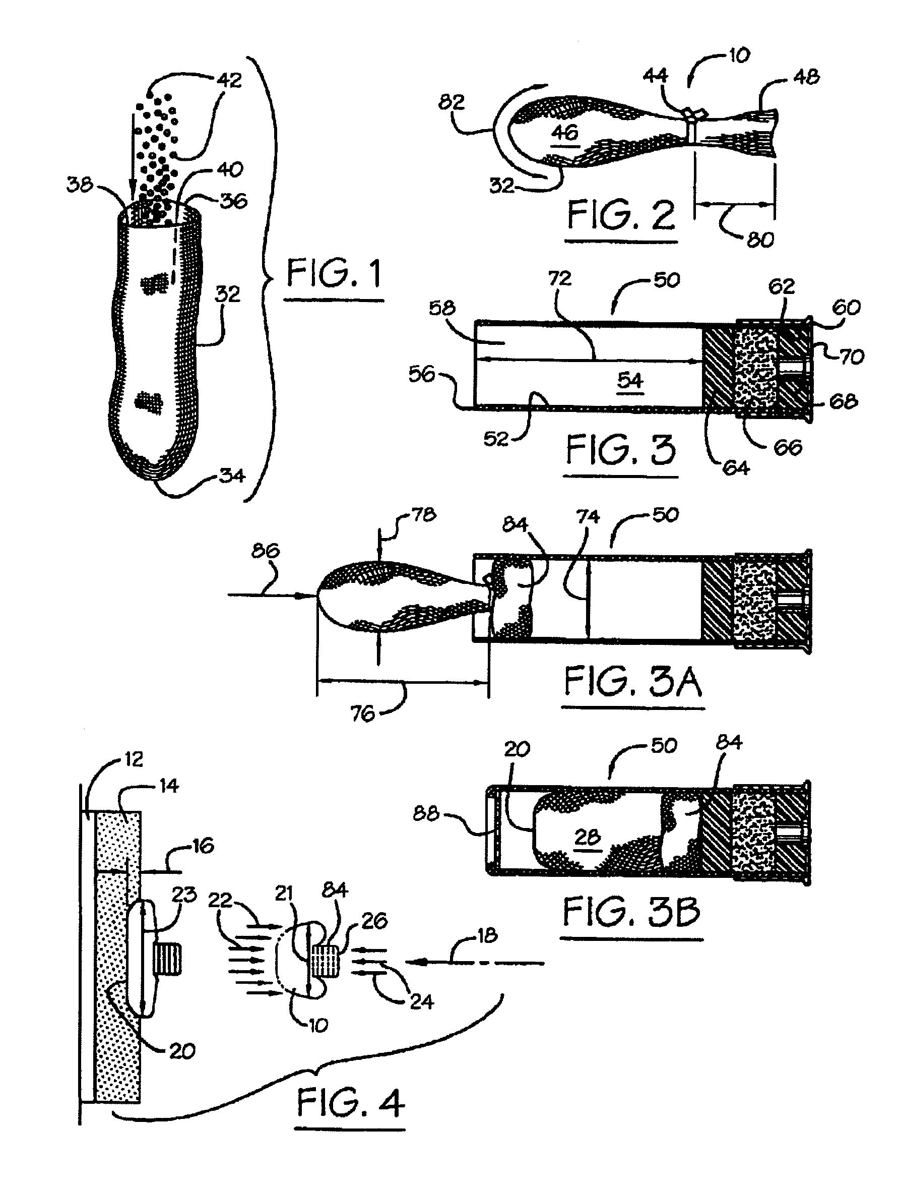
[0016]By way of one example of many to serve as background in understanding the present invention, in police management of an unruly crowd, even kept at bay by a barricade, it often escalates to a confrontation between the police and an individual crossing the barricade, which necessitates management of the individual. It is police standard operating procedure to limit force in such a confrontation commensurate to the danger posed. A first and lowest level of force dictated by the circumstances would be to strike the individual, typically at eight to twenty yards, with a low lethality munition, i.e., a munition that does not kill or seriously maim the individual. If, however, continuing with the example, the individual withdraws a concealed weapon, the use of a lethal munition would be dictated.

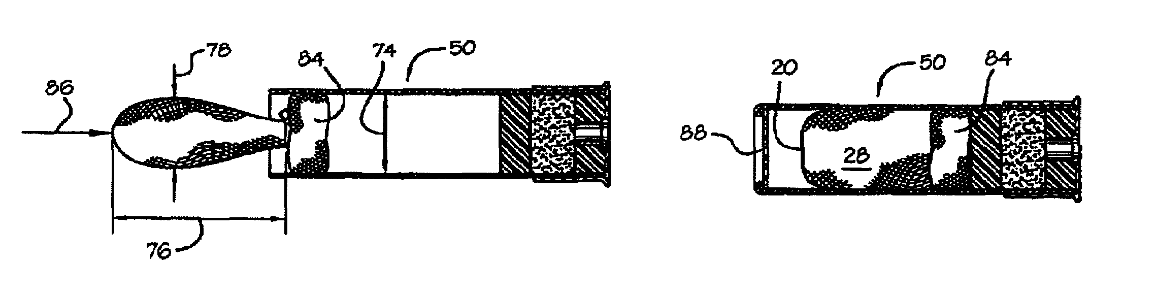
[0017]To qualify a munition as being of low lethality, and as best understood from FIG. 4, the projectile 10 is subjected to testing similar to the standard 0101.03 tests used by the National...


PUM


Abstract

An anti-personnel projectile launched from a weapon shell required at impact to have a low lethality consequence, in which the projectile is fitted in the shell in a shape characterized by a blunt end in the direction of flight and maintained in this shape by oppositely directed air resistance and propelling forces to obviate a change of shape during flight that might cause a serious injury.

Description

[0001]This is a continuation of U.S. application Ser. No. 10 / 873,331 filed Jun. 21, 2004 now U.S. Pat. No. 7,089,864, which is a continuation of U.S. application Ser. No. 10 / 114,726 filed Apr. 2, 2002 now U.S. Pat. No. 6,755,133, which is a continuation of earlier filed U.S. application Ser. No. 09 / 648,559 filed Aug. 28, 2000 now U.S. Pat. No. 6,374,742, which is a continuation-in-part of U.S. patent application Ser. No. 09 / 434,453 filed Nov. 5, 1999, now U.S. Pat. No. 6,202,562.BACKGROUND OF THE INVENTION[0002]1. Field of the Invention[0003]The present invention relates generally to projectiles used primarily for low lethality antipersonnel end use, as for example for crowd control by a municipality police force, and more particularly relates to improvements for assuring that a projectile in use will have the requisite low lethality consequence upon impact, and thus avoiding unintentional severe injury to any individual.[0004]2. Discussion of the Related Art[0005]The need for low l...

Claims


Application Information

Patent Timeline
IPC IPC(8): F42B12/34
CPCF42B12/34
Inventor BRUNN, MICHAELKRAVEL, JACOB
Owner COMBINED SYST
Why Eureka
Try Eureka