Check valves

Active Publication Date: 2008-11-04
GENERAL RUBBER LLC
View PDF15 Cites 29 Cited by
  • Summary
  • Abstract
  • Description
  • Claims
  • Application Information

AI Technical Summary

Benefits of technology

[0006]the valve wall including a bill extending longitudinally along the valve wall and terminating at a bill end contiguous with the outlet, the bill having a bill wall including laterally opposite lips extending in longitudinal and altitudinal directions adjacent the outlet and having a prescribed altitudinal extent, the bill wall including a transition portion extending longitudinally between the inlet and the lips, and the lips being biased in lateral directions into engagement with one another along a slit extending altitudinally across the bill adjacent the bill end such that the outlet normally is closed against backflow of the fluid into the passage through the outlet by engagement of the lips along the slit; and at least one fold in the bill wall, the fold extending longitudinally along a corresponding lip and, when in a folded configuration, including overlying legs extending across the bill in an essentially altitudinal direction, essentially parallel to the slit, so as to overlie the corresponding lip, the fold having a prescribed altitudinal extent and a prescribed longitudinal extent such that upon fluid entering the passage at the inlet and exerting fluid forces upon the valve wall at the bill to unfold the at least one fold and move the legs of the fold laterally, the relative dimensions of the altitudinal extent of the legs of the fold and the altitudinal extent of the bill enables unfolding of the at least one fold and lateral movement of the legs of the fold to part the lips in lateral directions and open the outlet to permit the flow of fluid from the inlet for discharge through an opening at the outlet of the valve member in response to minimum fluid forces upon the bill, and for providing the opening with an increased maximum available perimeter.
[0007]In addition, the present invention provides a check valve comprising: a flexible tubular valve member extending longitudinally between an inlet and a longitudinally opposite outlet, the flexible tubular valve member having a longitudinal passage for conducting a fluid from the inlet to the outlet, and a valve

Problems solved by technology

Duck-bill check valves, while relatively simple in design and construction, exhibit some drawbacks, especially when provided in the larger sizes employed in connection with large effluent pipes, such as those found in storm drain systems.
A common problem is inversion, that is, upon a build-up of back pressure at the outlet of the valve, the bill will tend to collapse and invert, thus opening the valve to backflow.
Attempts to stiffen

Method used


Image

  • Check valves
  • Check valves
  • Check valves

Examples


Example

DETAILED DESCRIPTION OF DRAWINGS

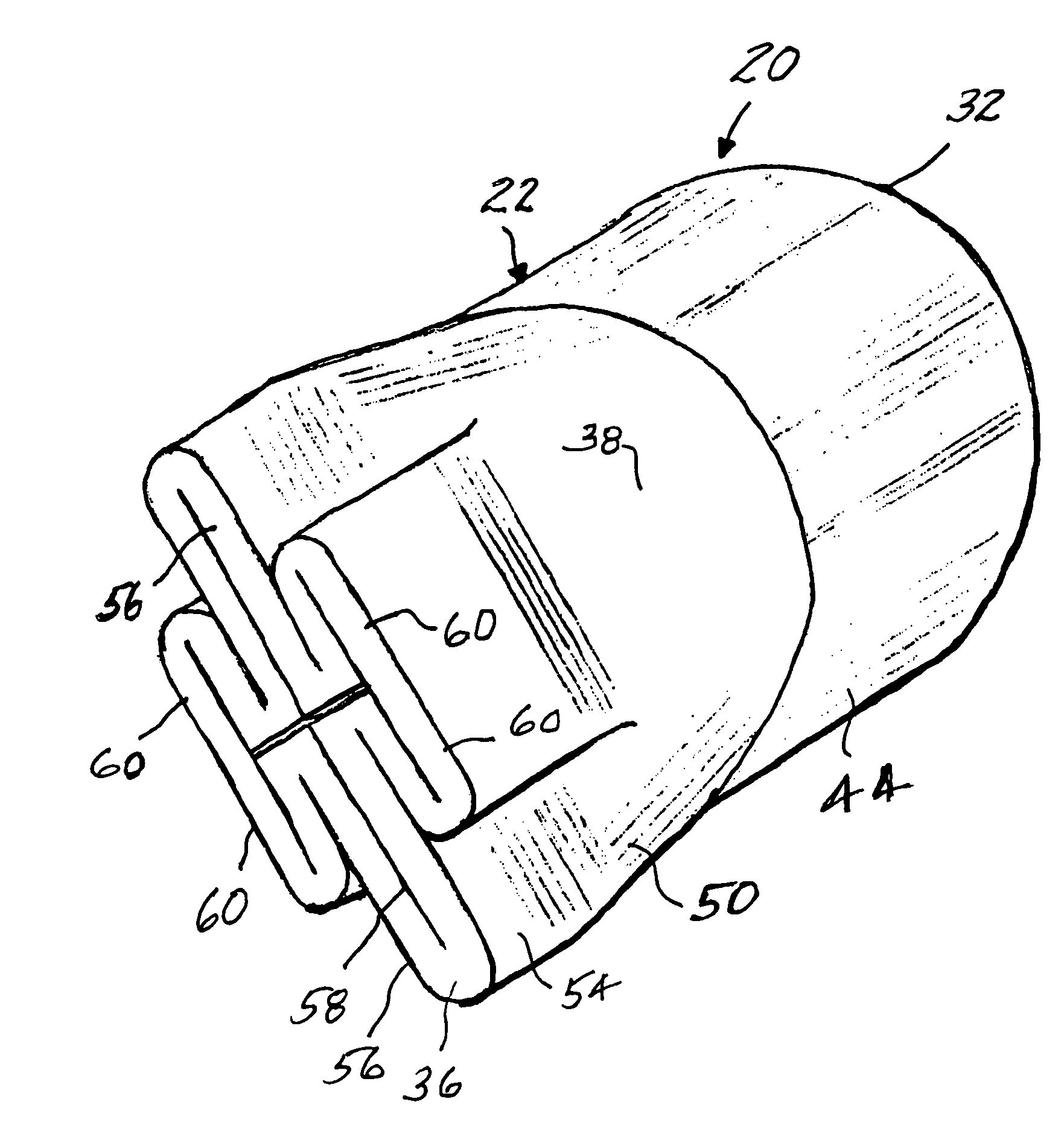
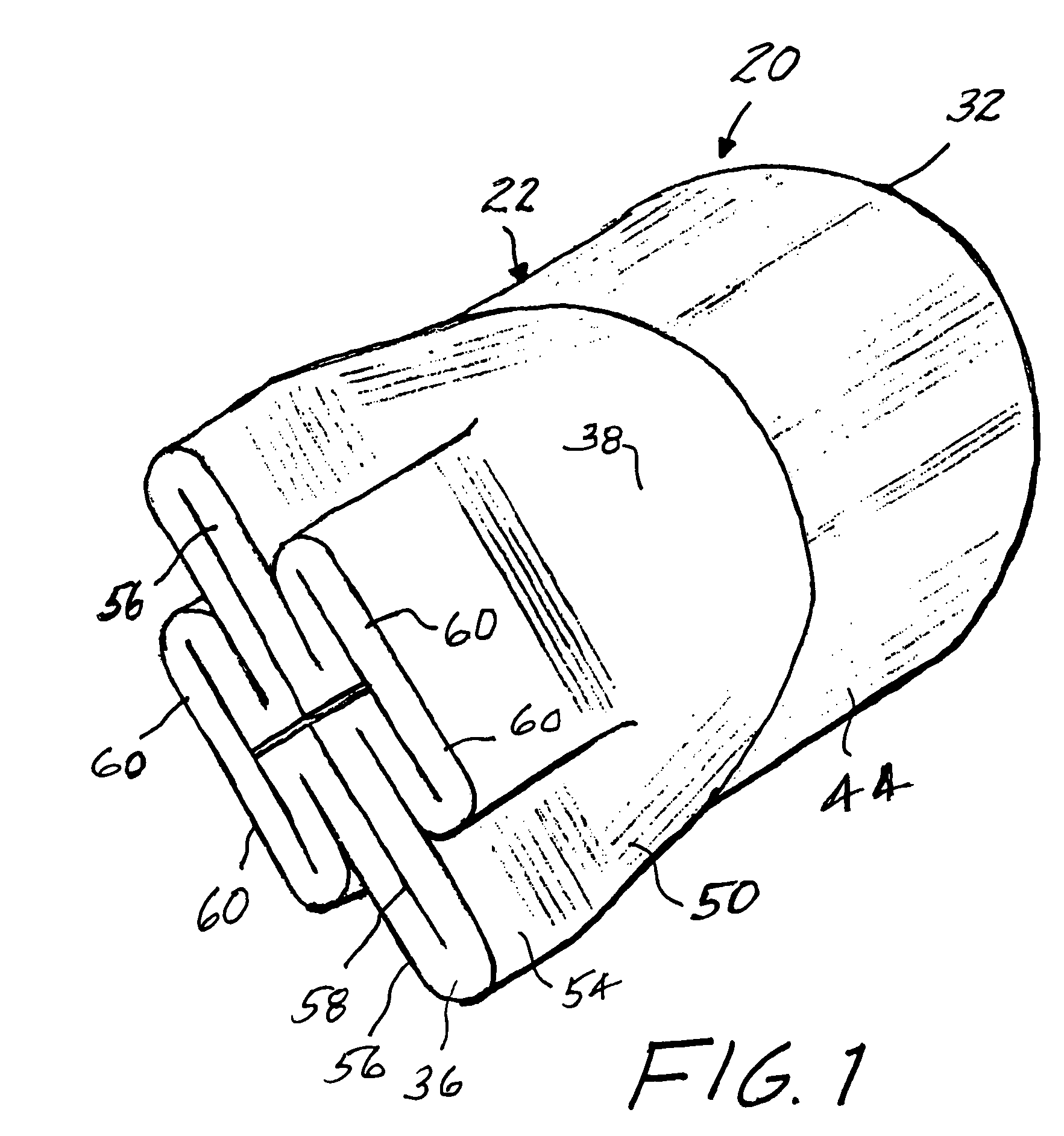
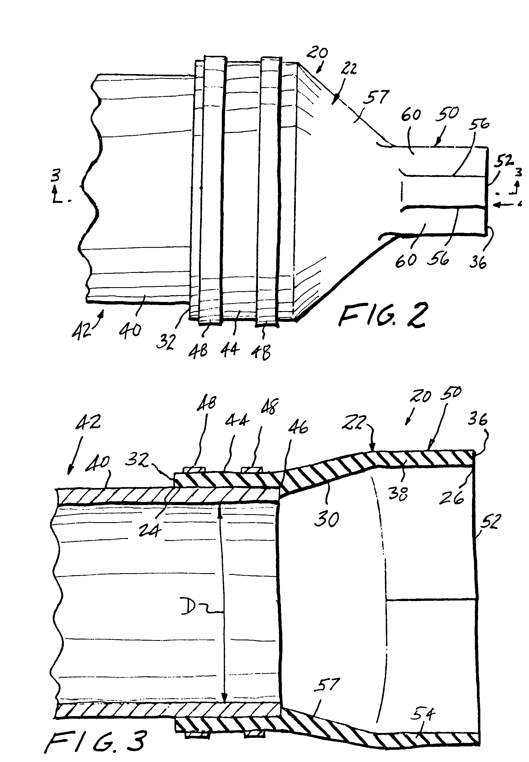
[0020]Referring now to the drawing, and especially to FIGS. 1 through 4 thereof, a check valve constructed in accordance with the present invention is shown at 20. Check valve 20 is of the duck-bill type and is seen to include a valve body in the form of a tubular valve member 22 constructed of a resiliently flexible material, usually in the form of an elastomeric material such as rubber or the like, as is now common in the manufacture of duck-bill type check valves. Valve member 22 extends longitudinally between an inlet 24 and a longitudinally opposite outlet 26 and has a longitudinal passage 30 for conducting a fluid from the inlet 24, which is located at upstream end 32 of the valve member 22, to the outlet 26, which is located at the downstream end 36 of the valve member 22. A valve wall 38 extends longitudinally from the inlet 24 to the outlet 26 and extends circumferentially around passage 30.

[0021]As seen in FIGS. 2 and 3, check valve 20 is co...


PUM


Abstract

Duck-bill type check valves each include an inlet, an outlet spaced longitudinally from the inlet, and a bill adjacent the outlet and having at least one fold extending longitudinally along the bill for enabling unfolding of the at least one fold to open the outlet and permit the flow of fluid from the inlet for discharge through an opening at the outlet in response to minimum fluid forces upon the bill, and to provide the opening with an increased maximum available perimeter.

Description

TECHNICAL FIELD[0001]The present invention relates generally to check valves and pertains, more specifically, to check valves of the type known as “duck-bill” check valves. More particularly, the invention provides improved duck-bill check valve configurations well suited for attachment to effluent pipes where it is desired to facilitate the passage of fluid from the pipe while preventing backflow into the pipe.BACKGROUND ART[0002]Check valves of the type known as “duck-bill” check valves have been used successfully for a very long time in the control of the flow of fluid where it is desired to pass fluid through a conduit in one direction and prevent flow in an opposite direction. In particular, duck-bill check valves have been coupled to effluent pipes to allow the flow of effluent out of such a pipe, while preventing reverse flow, or backflow, into the pipe as a result of a build-up of pressure downstream of the valve. These valves employ a resiliently flexible tubular valve body...

Claims


Application Information

Patent Timeline
IPC IPC(8): F16K15/14
CPCF16K15/147Y10T137/7843Y10T137/7882Y10T137/7885
Inventor AANONSEN, LLOYD B.CRADDOCK, WADE J.DIGIOVANNI, RICHARD J.
Owner GENERAL RUBBER LLC
Why Eureka
Try Eureka