

Parent-child leadframe type transformer
- Summary
- Abstract
- Description
- Claims
- Application Information
AI Technical Summary
Benefits of technology
Problems solved by technology
Method used
Image

Examples
Embodiment Construction
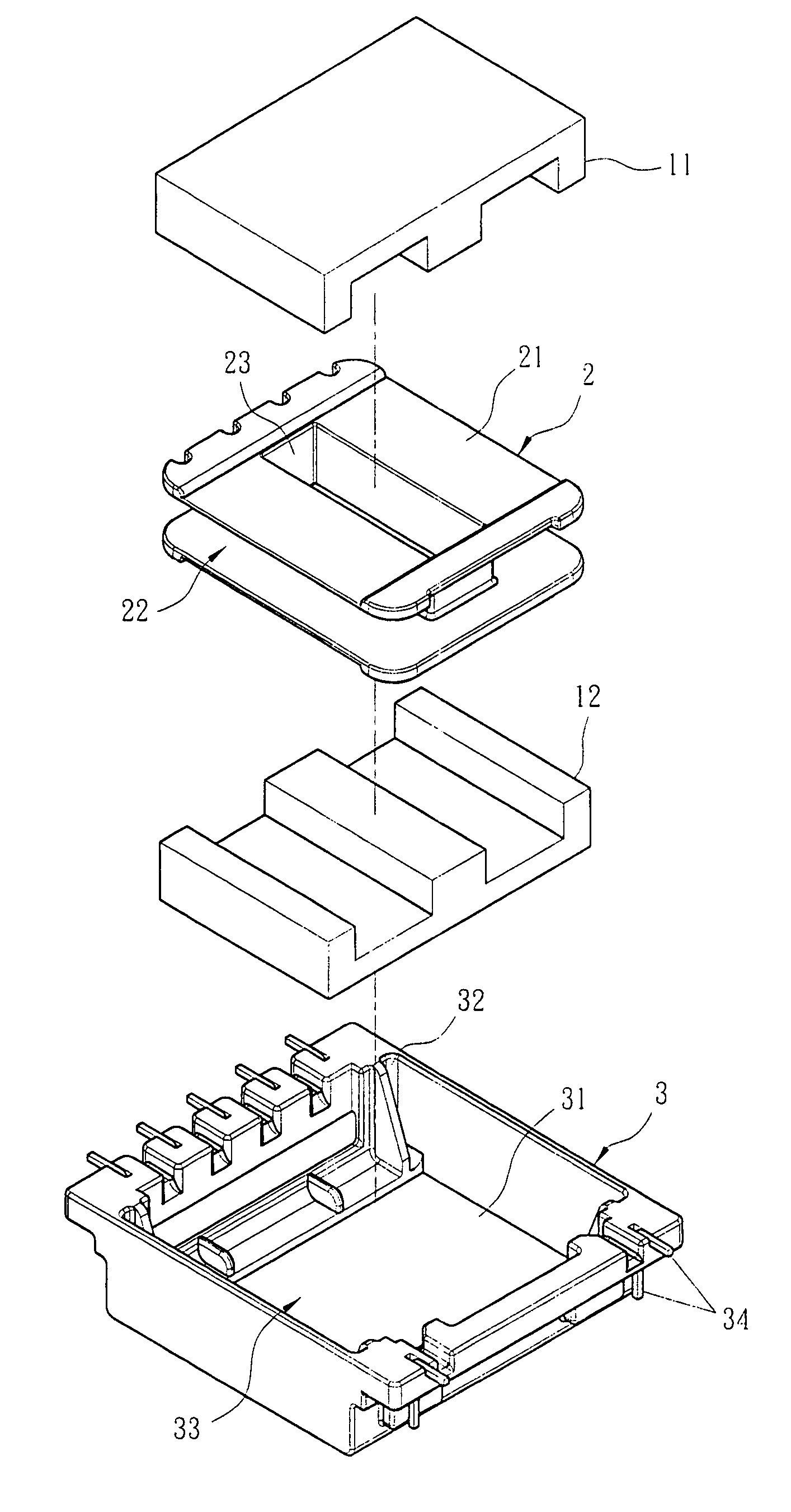
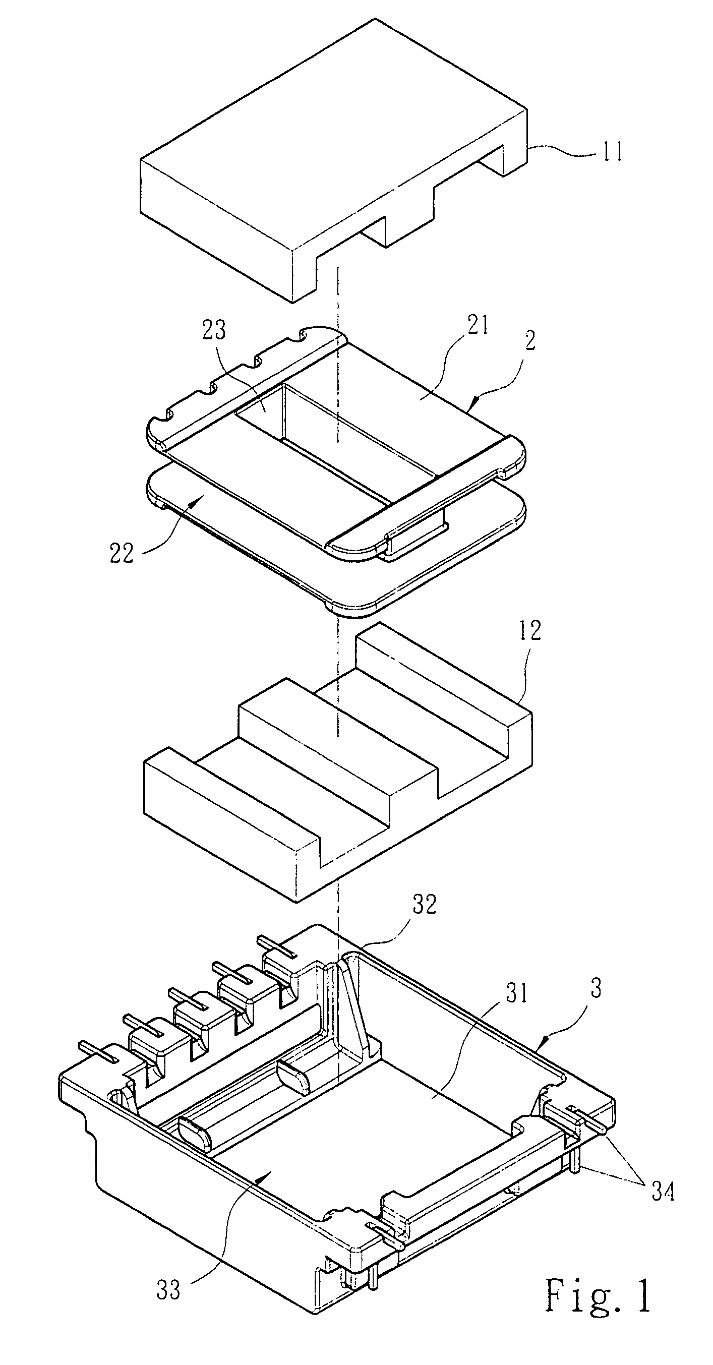
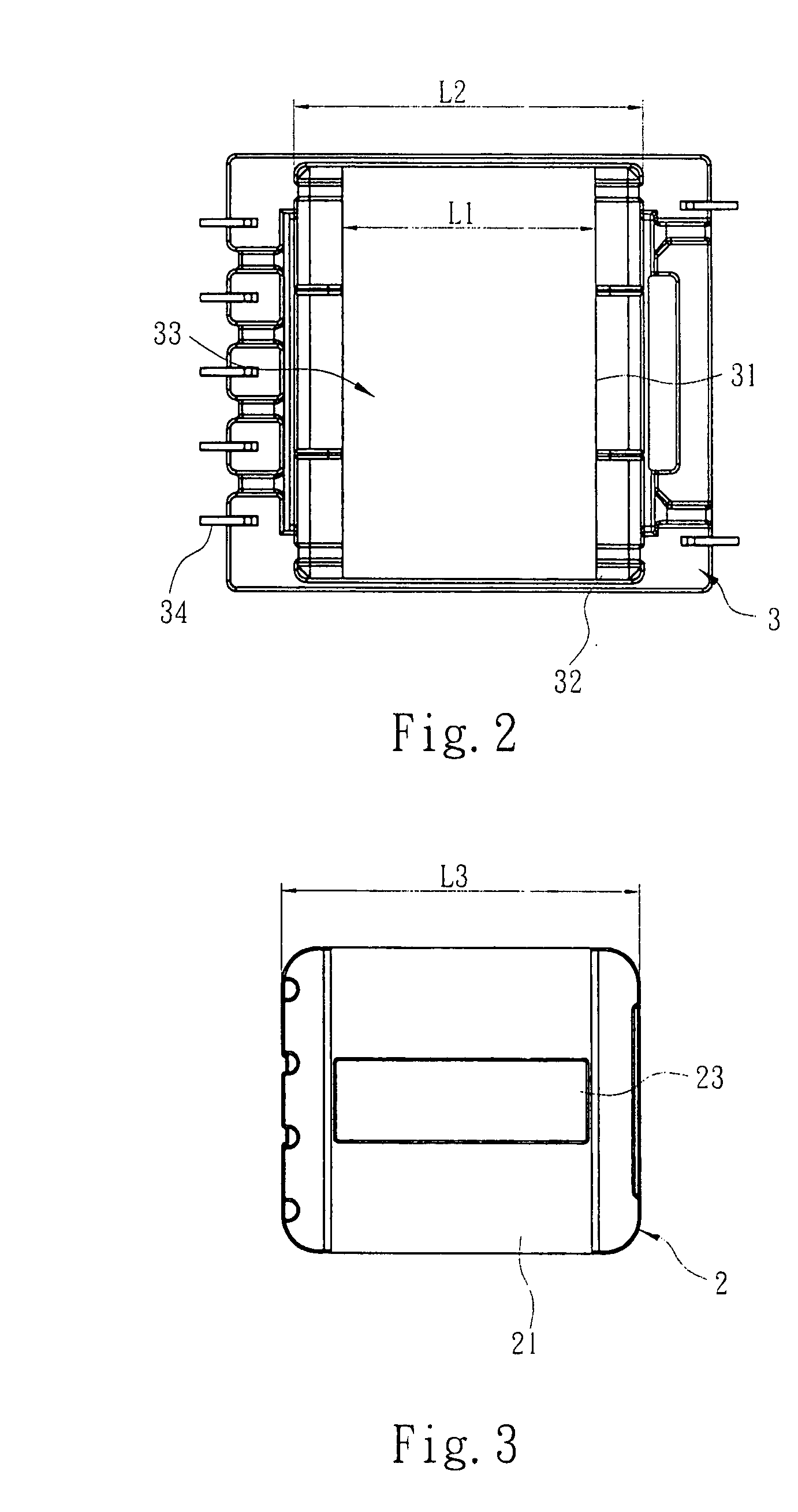
[0011]The technical contents of the invention will now be described in more detail hereinafter with reference to the accompanying drawings that show various embodiments of the invention, Referring to FIGS. 1 to 3 for an exploded view of the invention, a top view of a parent leadframe of the invention, and a top view of a child leadframe of the invention respectively, the invention comprises the elements such as two ferrite cores 11, 12 for forming a ferrite core module of electromagnetic induction medium, a child leadframe 2 and a parent leadframe 3. The child leadframe 2 includes at least two partitions 21, at least one coil winding slot 22 formed at an interval between the plurality of partitions 21 for winding conductive wires into a primary winding and at least one secondary winding, and a through hole 23 at the interval having the coil winding slot 22 for positioning two ferrite cores 11, 12 to form a magnetic closed loop. The two ferrite cores 11, 12 can be a pair of E-shape f...
PUM
 Abstract
Description
Claims
Application Information