Cushioning assembly in an athletic shoe

a technology for athletic shoes and cushioning, applied in the field of athletic shoes, can solve the problems of excessive force transmission directly to the foot, insufficient absorption of forces or energy, and impede the performance of the shoe, so as to reduce the possibility of bottoming out, reduce the possibility of maximum compression, and improve the stability of the shoe

Inactive Publication Date: 2008-11-11
K-SWISS
View PDF37 Cites 9 Cited by
  • Summary
  • Abstract
  • Description
  • Claims
  • Application Information

AI Technical Summary

Benefits of technology

[0005]It is an object of the invention to provide a cushioning assembly for use in athletic shoes. The assembly includes features providing cushioning as well as sufficient support to reduce the possibility of bottoming out (i.e., reducing the possibility of maximum compression being achieved such that the forces are directly transferred to the foot). Further, the arrangement includes features providing improved stability of the shoe, and a desirable “ride.”
[0006]According to one of the advantageous aspects of the invention, cushioning elements are provided in combination with a more rigid spring assembly or stiffening spring. According to the illustrated embodiment, the arrangement is in the form of a rigid spring or leaf spring assembly having cushioning elements disposed therein. The cushioning elements provide adequate cushioning or energy absorption while the more rigid spring or stiffening spring arrangement provides improved stability and minimizes the risk that the assembly will bottom out.
[0009]According to a still further aspect of the invention, an arrangement is provided to yield improved appearance characteristics while maintaining or even improving the stability of the shoe. In the illustrated embodiment, the more rigid spring assembly is provided at the exterior sides of the shoe, and the cushioning elements are visible through the rigid spring arrangement. This assembly allows the purchaser / user to view the cushioning elements and, because the cushioning elements are disposed within the more rigid spring, the ability to see these cushioning elements does not jeopardize the integrity of the shoe as could be the case with prior window arrangements. Further, in contrast to prior window-type arrangements, the aperture provided by the rigid spring allows for the direct viewing of the cushioning elements (i.e., the rigid springs are directly exposed to the exterior of the shoe and need not be viewed through a window pane). This arrangement can be advantageous in a number of respects. First, the arrangement allows the purchaser / user to actually touch and feel the cushioning elements. Second, the appearance can be superior in that window panes can tend to become scuffed or fatigued, which can detract from the appearance. Further, certain window pane arrangements can tend to distort or impair the view of the cushioning elements, particularly when viewing the cushioning elements from various angles. Other advantageous aspects of the display according to the invention are also provided as discussed in further detail herein.

Problems solved by technology

However, if a cushioning assembly is poorly designed, it can suffer from several disadvantages.
For example, if the arrangement is excessively soft, it can hinder the performance of the shoe, inadequately protect the foot from high impact forces, and / or the arrangement can be unstable which could potentially lead to injury.
Further, if the arrangement is excessively rigid, inadequate protection could also result in that the forces or energy is not sufficiently absorbed by the cushioning assembly such that excessive forces are transmitted directly to the foot.
Further, excessively stiff or rigid cushioning arrangements can also result in poor stability.
The ability to optimally balance the trade-off between soft / cushioning elements (which could bottom out) and stiff cushioning elements (which might not sufficiently absorb forces or energy) can be difficult.

Method used


Image

  • Cushioning assembly in an athletic shoe
  • Cushioning assembly in an athletic shoe
  • Cushioning assembly in an athletic shoe

Examples


Embodiment Construction

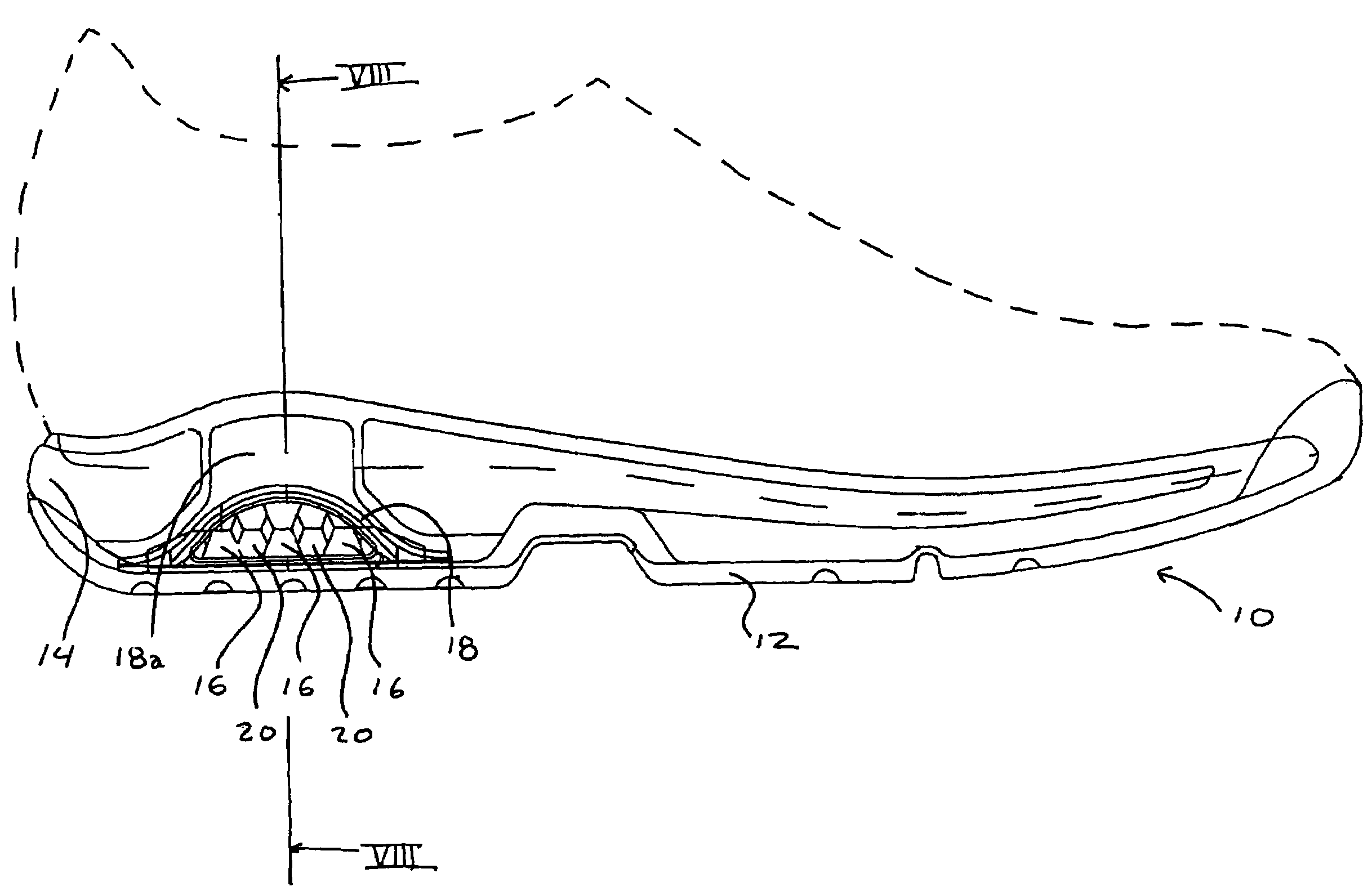
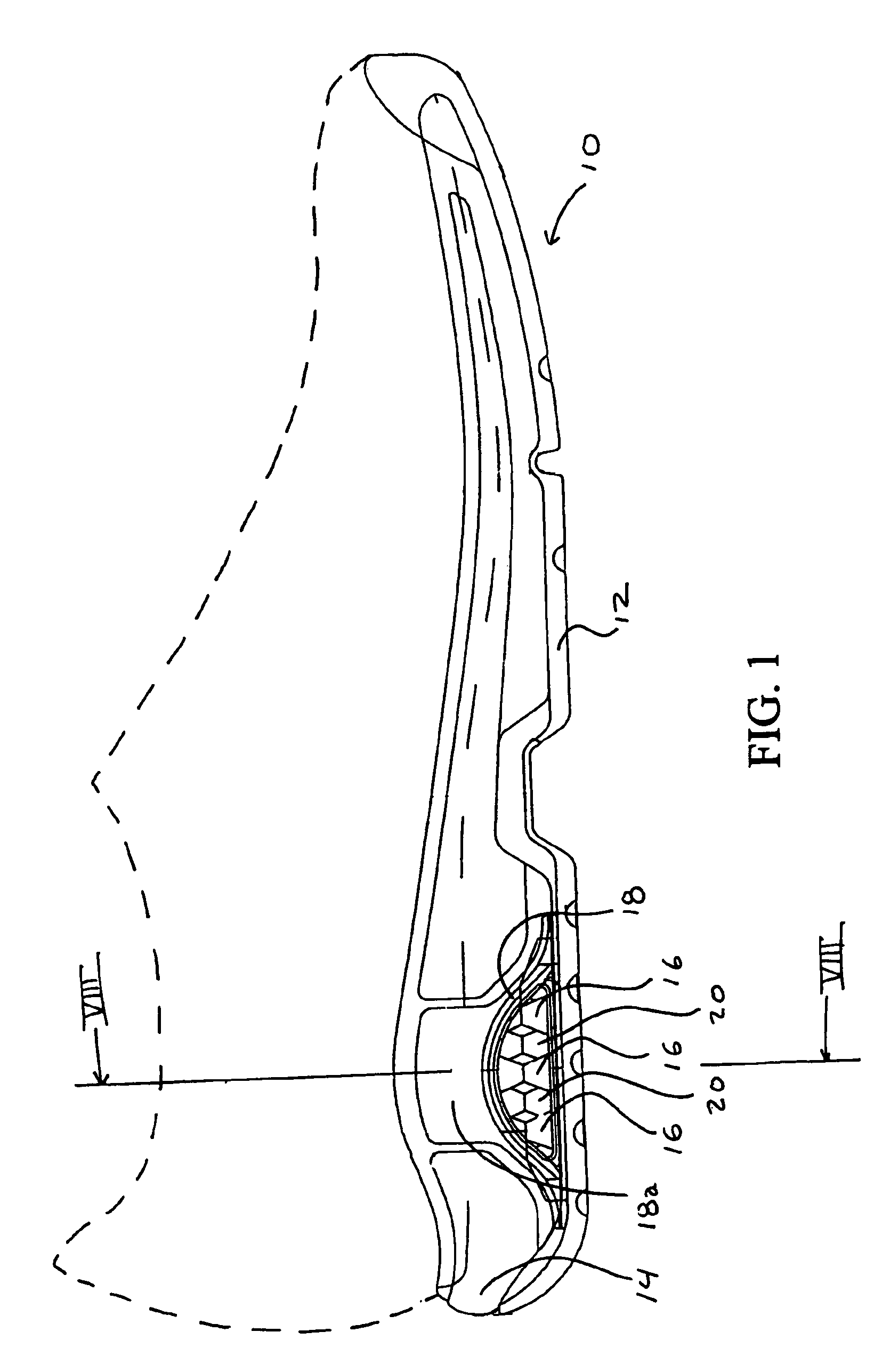
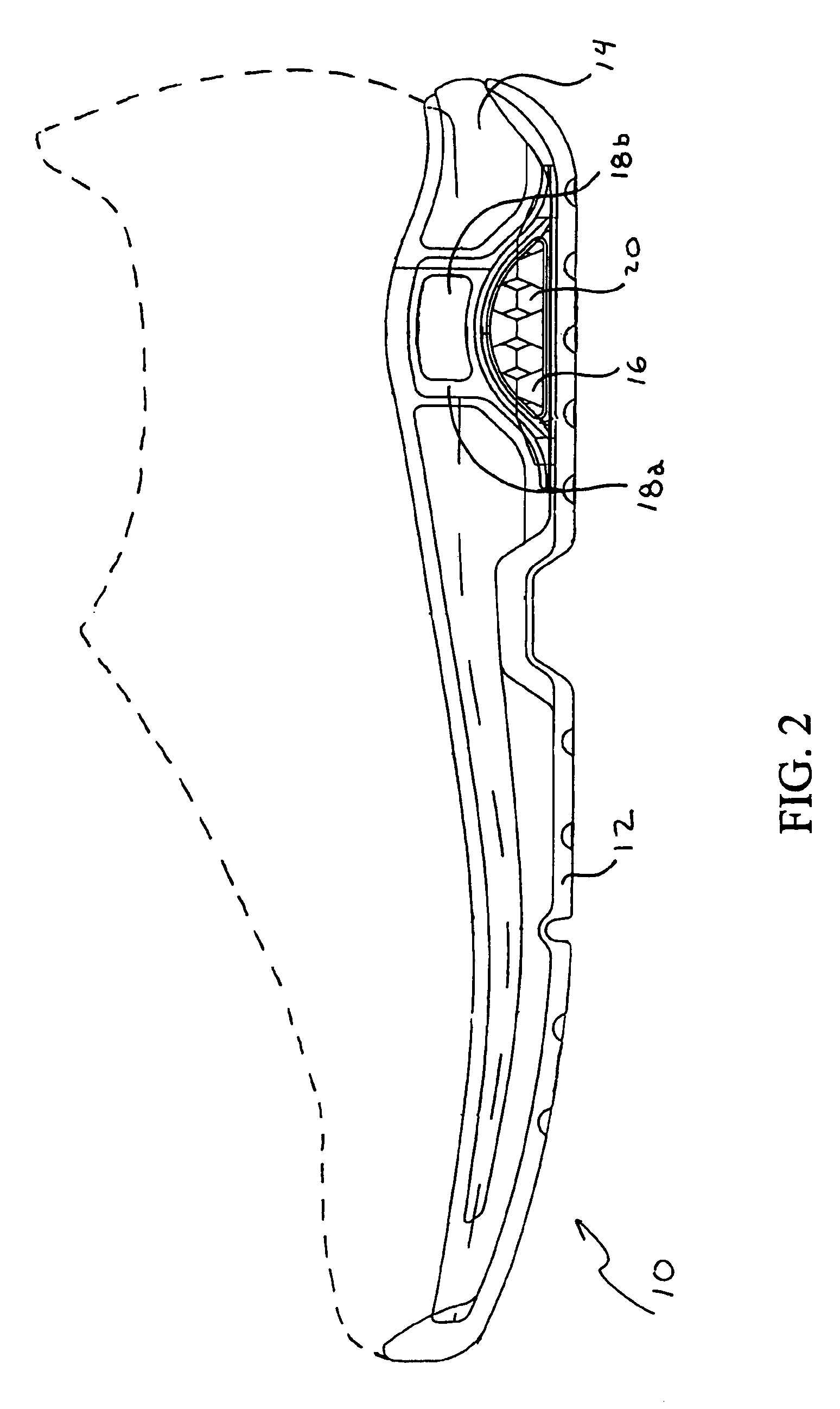
[0020]Referring to the drawings, wherein like reference numerals designate like or corresponding parts throughout the several views, a preferred embodiment of the invention will be described. However, it is to be understood that the embodiment is provided as an example, and it should be apparent that other embodiments are possible and each and every feature of the illustrated embodiment need not be utilized in accordance with the invention. For example, as will be described herein, three different cushioning arrangements or assemblies are provided across the width of the shoe in five different regions across the width. However, a different number of cushioning arrangements (or types of cushioning arrangements) could be provided. Also, although the cushioning assembly is preferably provided in the heel region of the shoe, features of the invention could also be advantageously utilized in other regions of the shoe as well.

[0021]Referring to FIGS. 1 and 2, medial and lateral sides of t...


PUM

PropertyMeasurementUnit
stiffnessaaaaaaaaaa
widthaaaaaaaaaa
lengthaaaaaaaaaa

Abstract

An athletic shoe includes a sole assembly and a cushioning arrangement disposed within the sole assembly. The cushioning arrangement includes a cushioning element, and a stiffening spring at least partially surrounding the cushioning element. The spring has a stiffness greater than the cushioning element. The athletic shoe can include a sole assembly having cushioning arrangements provided across a width of the sole assembly. In a preferred arrangement, similar cushioning assemblies are disposed on medial and lateral sides of the shoe, with three additional cushioning assemblies provided between the lateral and medial assemblies. Each of the lateral and medial assemblies can include a stiffening spring that at least partially surrounds at least one cushioning element.

Description

FIELD OF THE INVENTION[0001]The invention relates to athletic shoes, and particularly to a cushioning arrangement or cushioning assembly for athletic shoes. Although the cushioning assembly is particularly advantageous for use in a heel region of the shoe, the assembly or certain aspects of the assembly could be utilized in other portions of the shoe.BACKGROUND OF THE INVENTIONDISCUSSION OF BACKGROUND[0002]A wide variety of cushioning arrangements have been available in athletic shoes. The cushioning arrangements are generally designed to absorb energy in order to protect the foot. However, if a cushioning assembly is poorly designed, it can suffer from several disadvantages. For example, if the arrangement is excessively soft, it can hinder the performance of the shoe, inadequately protect the foot from high impact forces, and / or the arrangement can be unstable which could potentially lead to injury. Further, if the arrangement is excessively rigid, inadequate protection could also...

Claims


Application Information

Patent Timeline
Patent Type & Authority Patents(United States)
IPC IPC(8): A43B13/28A43B13/18A43B21/26
CPCA43B13/181A43B21/26
Inventor PRESKAR, DAVID JOSEPHLIU, KENNETH J.JELLEY, GRAHAM
Owner K-SWISS
Why Eureka
Try Eureka