Method and system for return of drilling fluid from a sealed marine riser to a floating drilling rig while drilling
What is AI technical title?
AI technical title is built by Patsnap AI team. It summarizes the technical point description of the patent document.
a technology of floating structure and riser, which is applied in the direction of drilling pipes, drilling/well accessories, sealing/packing, etc., can solve the problems of significant rig downtime, environmental problems, and the possibility of over-sealing of these joints, so as to reduce the vertical movement
Inactive Publication Date: 2008-11-11
WEATHERFORD TECH HLDG LLC
View PDF338 Cites 53 Cited by
Summary
Abstract
Description
Claims
Application Information
AI Technical Summary
This helps you quickly interpret patents by identifying the three key elements:
Problems solved by technology
Method used
Benefits of technology
Benefits of technology
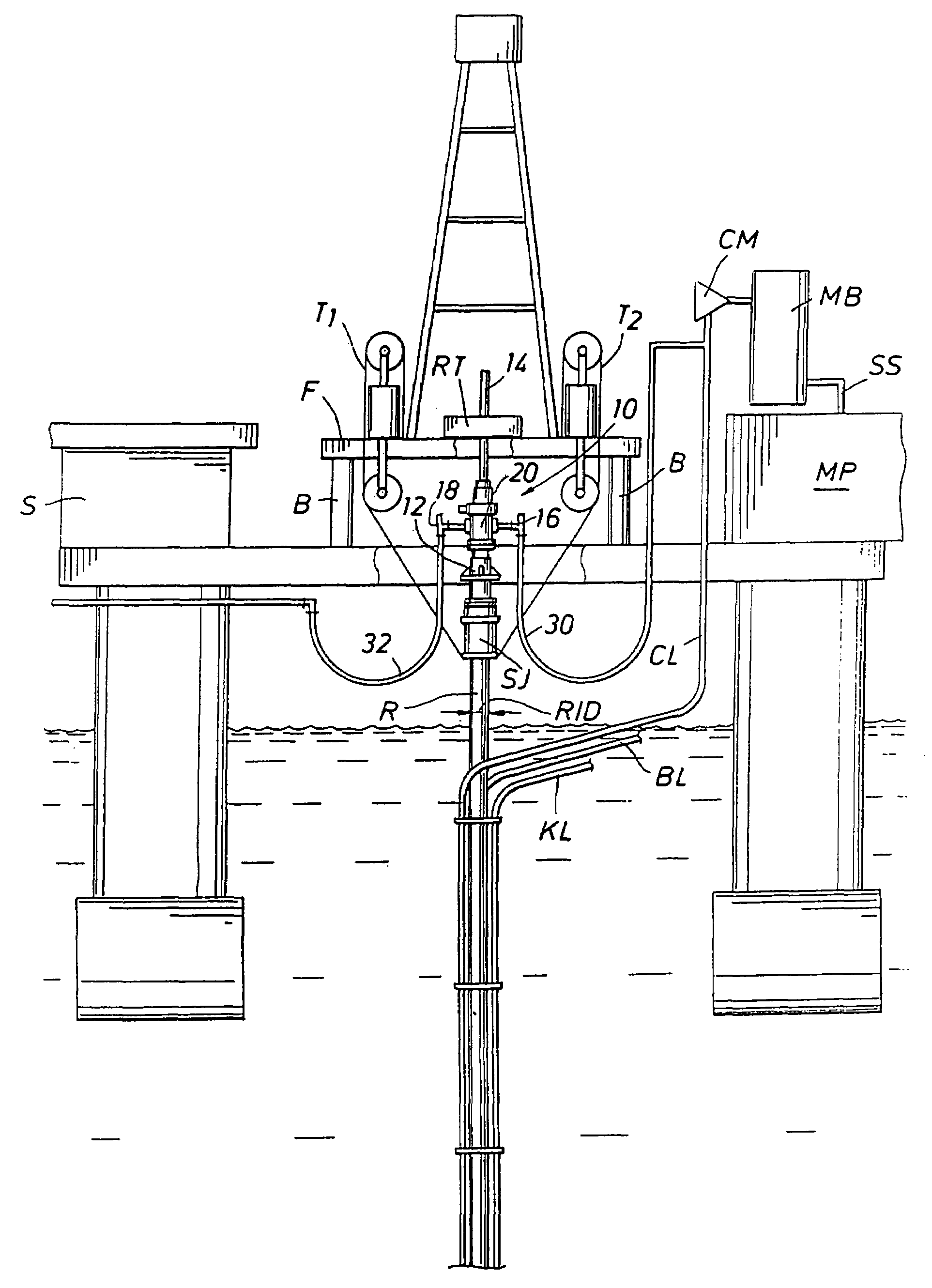
[0011]A system is disclosed for use with a floating rig or structure for drilling in the floor of an ocean using a rotatable tubular. A seal housing having a rotatable seal is connected to the top of a marine riser fixed to the floor of the ocean. The seal housing includes a first housing opening sized to discharge drilling fluid pumped down the rotatable tubular and then moved LIP the annulus of the riser. The seal rotating with the rotatable tubular allows the riser and seal housing to maintain a predetermined pressure in the fluid or mud return system that is desirable in underbalanced drilling, gas-liquid mud systems and pressurized mud handling systems. A flexible conduit or hose is used to compensate for the relative movement of the seal housing and the floating structure since the floating structure moves independent of the seal housing. This independent movement of seal housing relative to the floating structure allows the seal rotating with the tubular to experience reduced vertical movement while drilling.
Problems solved by technology
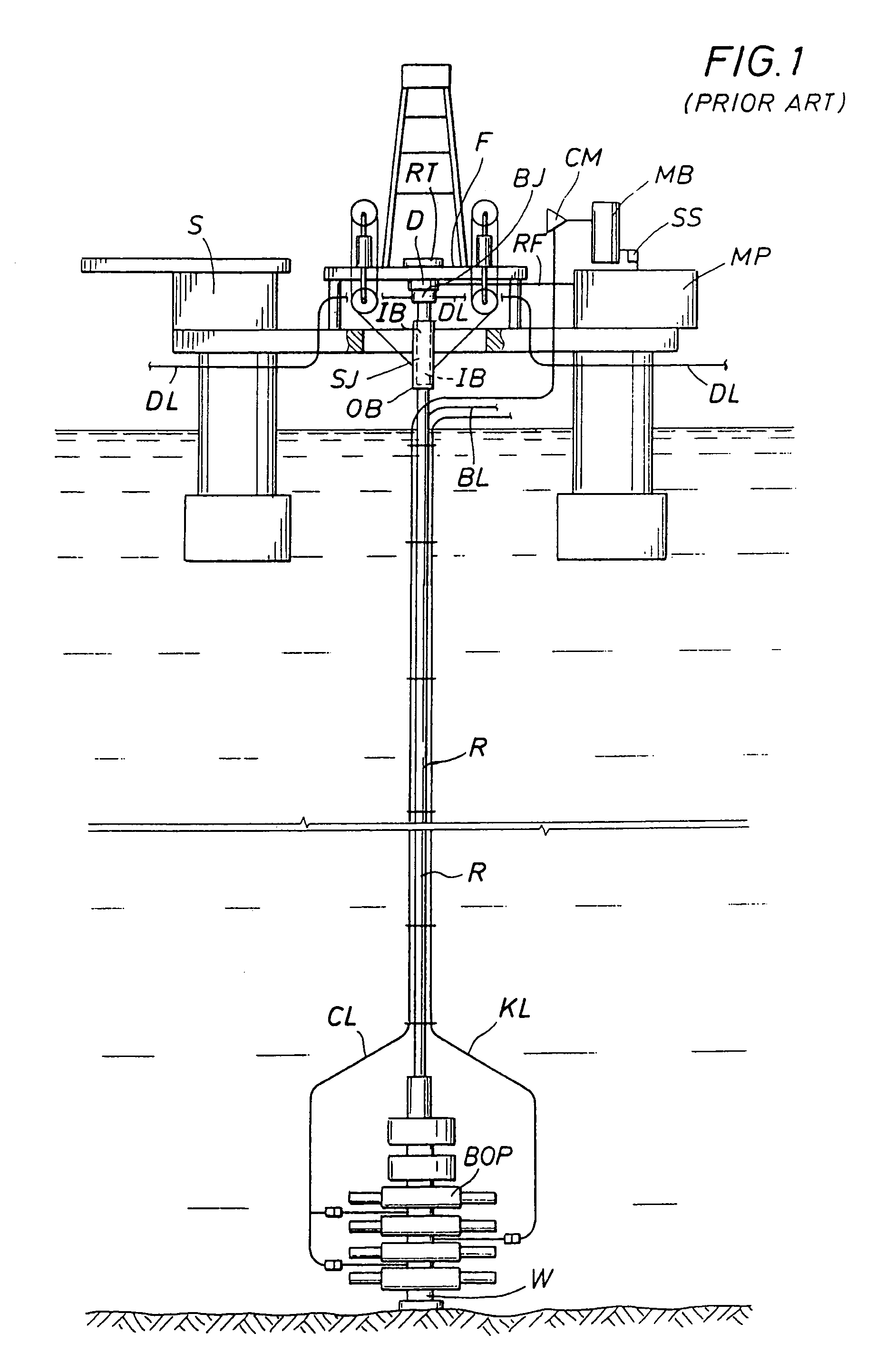
If the joints need replacement, significant rig down-time can be expected.
Also, the seal pressure rating for these joints may be exceeded by emerging and existing drilling techniques that require surface pressure in the riser mud return system, such as in underbalanced operations comprising drilling, completions and workovers, gas-liquid mud systems and pressurized mud handling systems.
Both the open bell-nipple and seals in the slip and ball joints create environmental issues of potential leaks of fluid.
Method used
Image
Click on the blue label to locate the original text in one second.
Reading with bidirectional positioning of images and text.
Examples
Embodiment Construction
[0028]FIGS. 2, 3B and 6 to 8 disclose the preferred embodiment of the present invention and FIG. 4 shows an embodiment of the invention for use of a conventional diverter and slip and ball joints after removing the bearing and seal assembly of the present invention as illustrated in FIG. 5, from the seal housing, as will be discussed below in detail.
[0029]FIG. 2 illustrates a rotating blowout preventer or rotating control head, generally designated as 10, of the present invention. This rotating blowout preventer or rotating control head 10 is similar, except for modifications to be discussed below, to the rotating blowout preventer disclosed in U.S. Pat. No. 5,662,181, assigned to the assignee of the present invention, Weatherford / Lamb, Inc. of Houston, Tex. The '181 patent, incorporated herein by reference for all purposes, discloses a product now available from the assignee that is designated Model 7100. The modified rotating blowout preventer 10 can be attached above the riser R,...
PUM
Abstract
A floating rig or structure for drilling in the floor of an ocean using a rotatable tubular includes a seal housing having a rotatable seal connected above a portion of a marine riser fixed to the floor of the ocean. The seal rotating with the rotating tubular allows the riser and seal housing to maintain a predetermined pressure in the system that is desirable in underbalanced drilling, gas-liquid mud systems and pressurized mud handling systems. The seal is contemplated to be either an active seal or a passive seal. A flexible conduit or hose is used to compensate for relative movement of the seal housing and the floating structure because the floating structure moves independent of the seal housing. A method for use of the system is also disclosed.
Description
CROSS-REFERENCE TO RELATED APPLICATIONS[0001]This application is a continuation of U.S. application Ser. No. 09 / 911,295, filed Jul. 23, 2001, now U.S. Pat. No. 6,913,092, which is a continuation-in-part of U.S. application Ser. No. 09 / 260,642, filed Mar. 2, 1999, now U.S. Pat. No. 6,263,982, on Jul. 24, 2001, which is a continuation-in-part of U.S. application Ser. No. 09 / 033,190, filed Mar. 2, 1998, now U.S. Pat. No. 6,138,774, which are incorporated herein for reference.BACKGROUND OF THE INVENTION[0002]1. Field of the Invention[0003]The present invention relates to a method and system for a floating structure using a marine riser while drilling. In particular, the present invention relates to a method and system for return of drilling fluid from a sealed marine riser to a floating structure while drilling in the floor of an ocean using a rotatable tubular.[0004]2. Description of the Related Art[0005]Marine risers extending from a wellhead fixed on the floor of an ocean have been u...
Claims
Application Information
Patent Timeline
Application Date:The date an application was filed.
Publication Date:The date a patent or application was officially published.
First Publication Date:The earliest publication date of a patent with the same application number.
Issue Date:Publication date of the patent grant document.
PCT Entry Date:The Entry date of PCT National Phase.
Estimated Expiry Date:The statutory expiry date of a patent right according to the Patent Law, and it is the longest term of protection that the patent right can achieve without the termination of the patent right due to other reasons(Term extension factor has been taken into account ).
Invalid Date:Actual expiry date is based on effective date or publication date of legal transaction data of invalid patent.

