
Carriage for receiving molten metal with a mechanism for moving a ladle up and down, and a method for transporting molten metal

a technology for receiving molten metal and transporting metal, which is applied in the direction of lighting and heating equipment, furniture, charge manipulation, etc., can solve the problems of large foundry, large ladle that is suspended by the crane, and accidental fall of the ladl

Active Publication Date: 2017-08-17
SINTOKOGIO LTD +1
View PDF1 Cites 5 Cited by
  • Summary
  • Abstract
  • Description
  • Claims
  • Application Information

AI Technical Summary

Benefits of technology

The patent describes a device for safely and efficiently receiving and transporting molten metal. The device includes a ladle that is moved up and down by a frame, allowing for leveling of the pouring level and easy access to the ladle. The frame is suspended at two locations by chains, making it well balanced and safe from molten metal leakage. The motor of the device for moving the frame is placed separately from the ladle, preventing any damage by molten metal leakage. The device also includes a mechanism for opening a cover to maintain the temperature of the molten metal and a mechanism for moving the ladle up and down, reducing the vertical movement of the cover-opening mechanism and making it smaller. The motors are located above the ladle, preventing the risk of damage by molten metal leakage. Overall, the device provides a safe and efficient method for receiving and transporting molten metal.

Problems solved by technology

However, when the ladle that contains molten metal at a high temperature is transported by a crane, there are problems such that an operator must approach the high temperature molten metal, and such that the ladle that is suspended by the crane may accidentally fall.
However, a foundry is generally very large, and so the time when the melting furnace or the holding furnace is installed may differ from the time when the system for pouring the molten metal is installed.

Method used


Image

  • Carriage for receiving molten metal with a mechanism for moving a ladle up and down, and a method for transporting molten metal
  • Carriage for receiving molten metal with a mechanism for moving a ladle up and down, and a method for transporting molten metal
  • Carriage for receiving molten metal with a mechanism for moving a ladle up and down, and a method for transporting molten metal

Examples


Embodiment Construction

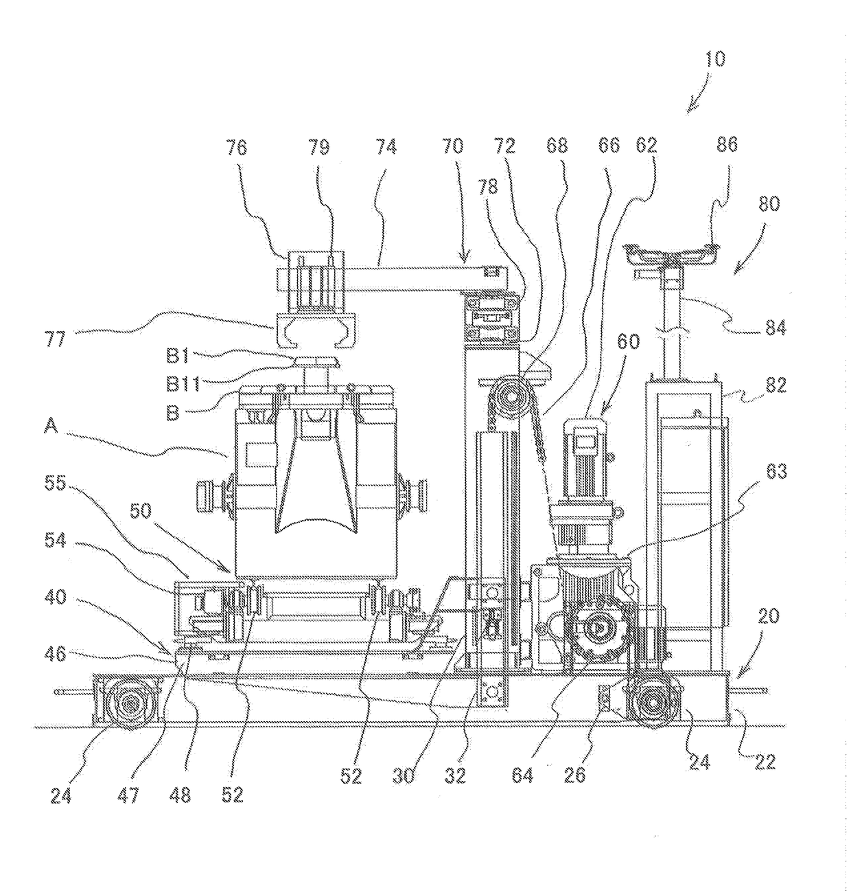
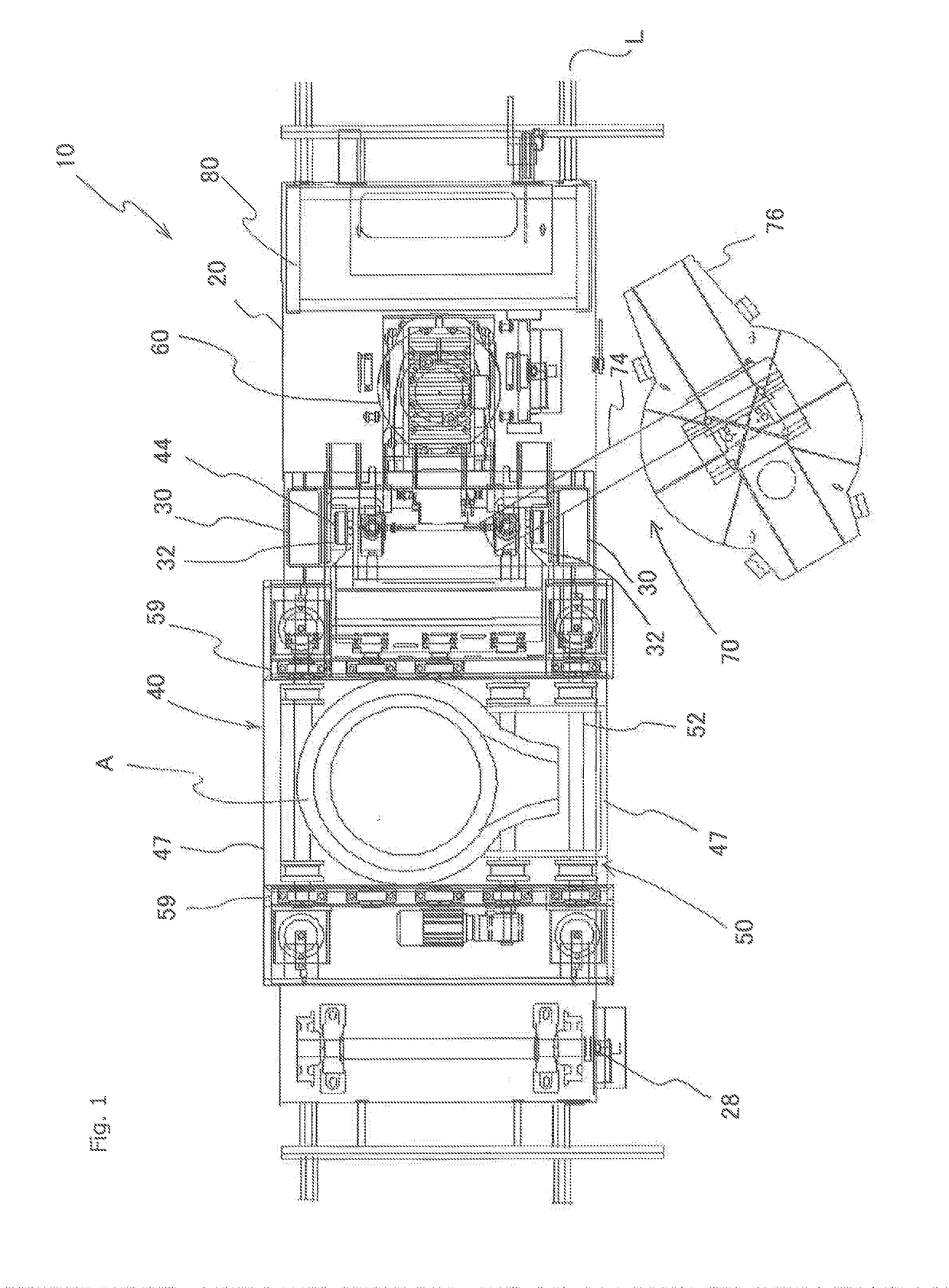
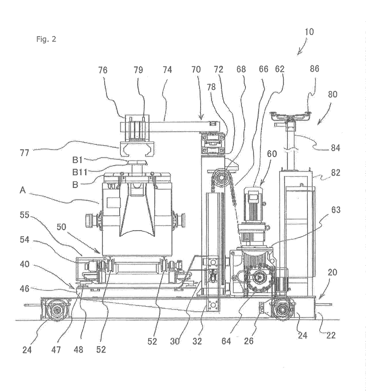
[0041]Below, a carriage 10 for receiving molten metal with a mechanism for moving a ladle up and down of an embodiment of the present invention is discussed with reference to the appended drawings. In the drawings, the same numeral or symbol is used for the elements that correspond to, or are similar to, each other. Thus duplicate descriptions are omitted. FIG. 1 is a plan view of the carriage 10 for receiving molten metal, as an embodiment of the present invention. FIGS. 2 and 3 are front views of it (viewed from the bottom in FIG. 1). In FIGS. 2 and 3 a part of a device 70 for opening a cover, which is shown in FIG. 1, is omitted. The carriage 10 moves a ladle A up and down, which ladle A receives molten metal from a furnace, such as a melting furnace or a holding furnace (in this embodiment, a melting furnace), and transports it along a route. FIG. 2 shows the ladle A that is moved down and FIG. 3 shows one that is moved up. In FIG. 3 a cover B for the ladle A is removed. The mel...


PUM

PropertyMeasurementUnit
Weightaaaaaaaaaa
Heightaaaaaaaaaa

Abstract

To provide a carriage for receiving molten metal with a mechanism for moving a ladle up and down and a method for transporting molten metal to safely move a ladle for receiving a molten metal up and down and transport it. The carriage (10) for receiving molten metal to transport the ladle that receives molten metal from a furnace (C) comprises a carriage (20) for travelling on a route (L), guiding columns (30) that are placed on the carriage (20), a frame (40) that horizontally extends from the guiding columns and moves up and down above the carriage (20), a mechanism (50) for moving the ladle, which mechanism is placed on the frame (40) and horizontally moves the ladle, and the driver (60) for moving the frame up and down.

Description

TECHNICAL FIELD[0001]The present invention relates to a carriage for receiving molten metal and a method for transporting molten metal, so as to transport a ladle that receives molten metal from a furnace. Especially, it relates to a carriage for receiving molten metal with a mechanism for moving a ladle up and down, and a method for transporting molten metal with a ladle being moved up and down.BACKGROUND ART[0002]In a foundry, cast products are manufactured by transporting molten metal at a high temperature that has been melted in a melting furnace or the like to a system for pouring the molten metal and by pouring the molten metal into molds by means of the system for pouring the molten metal. Conventionally, to transport molten metal from a melting furnace to a system for pouring the molten metal, the molten metal is received by a ladle. Then the ladle is transported to the system for pouring the molten metal by means of a crane. However, when the ladle that contains molten meta...

Claims


Application Information

Patent Timeline
IPC IPC(8): B22D41/12F27D3/06
CPCB22D41/12F27D2003/0091F27D2003/0086F27D3/06F27D3/123F27D2003/125F27D2003/127
Inventor NISHIDA, TADASHIHOSHINO, MASANORI
Owner SINTOKOGIO LTD
Learn More