Surgical forceps which can be taken apart

Active Publication Date: 2014-03-27
WALDEMAR LINK GMBH & CO
View PDF9 Cites 6 Cited by
  • Summary
  • Abstract
  • Description
  • Claims
  • Application Information

AI Technical Summary

Benefits of technology

[0007]Accordingly, an aspect of the invention is providing a pair of forceps or scissors which has a pivot joint, can be taken ap

Problems solved by technology

As a result, bacteria and viruses ar

Method used


Image

  • Surgical forceps which can be taken apart
  • Surgical forceps which can be taken apart
  • Surgical forceps which can be taken apart

Examples


Example

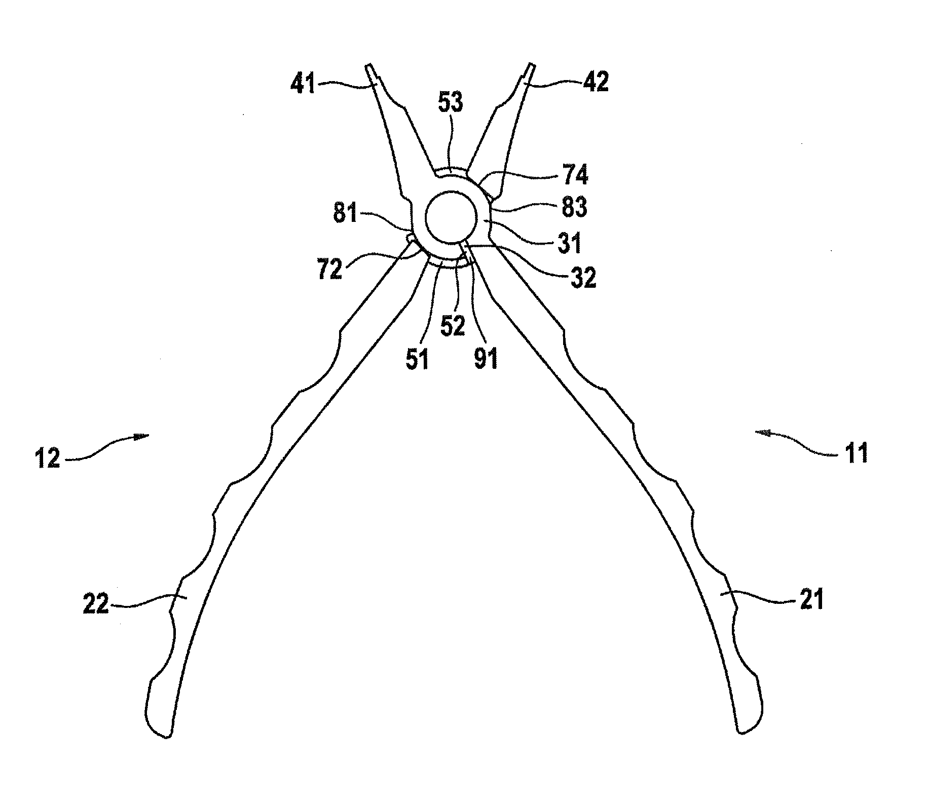
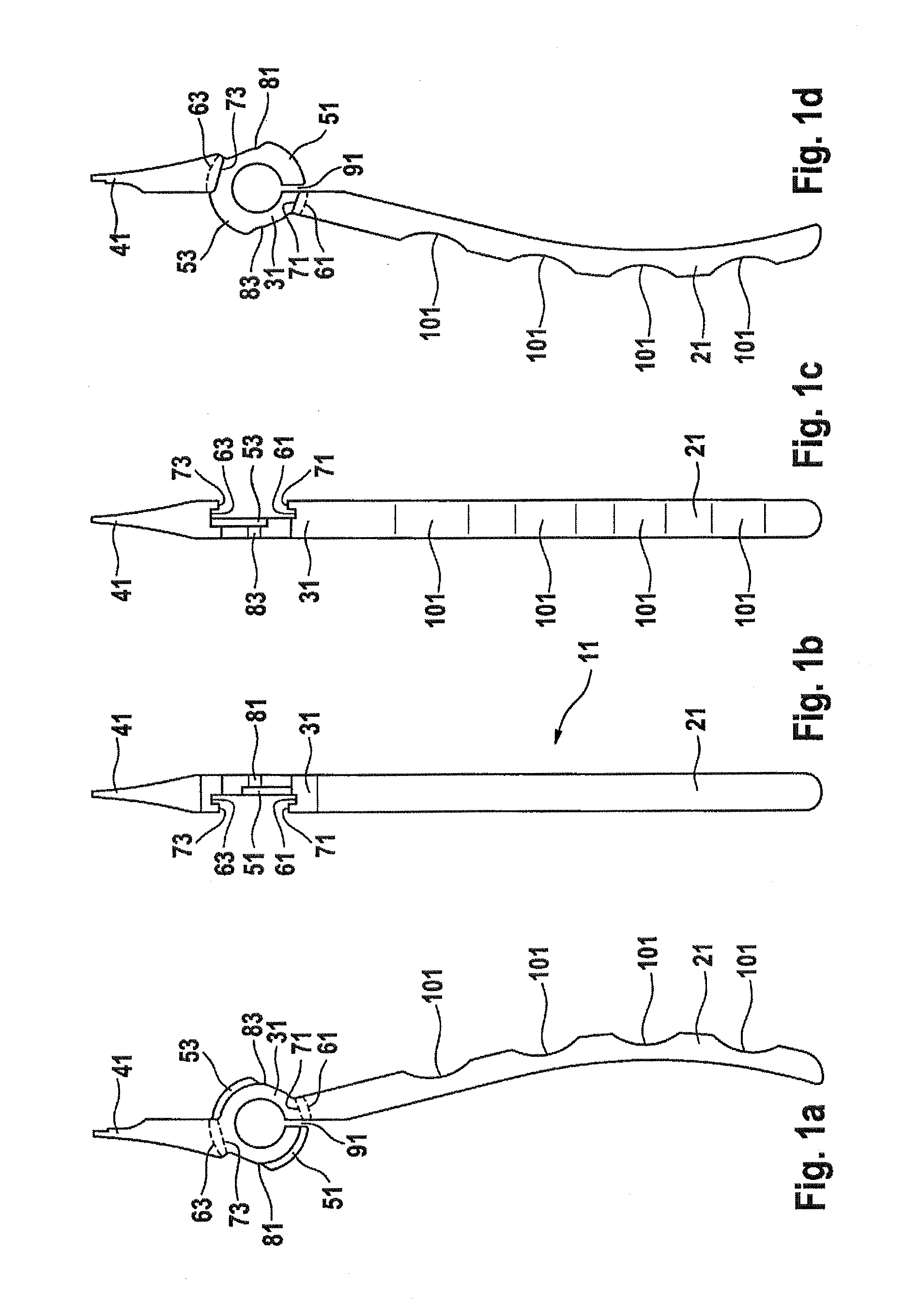
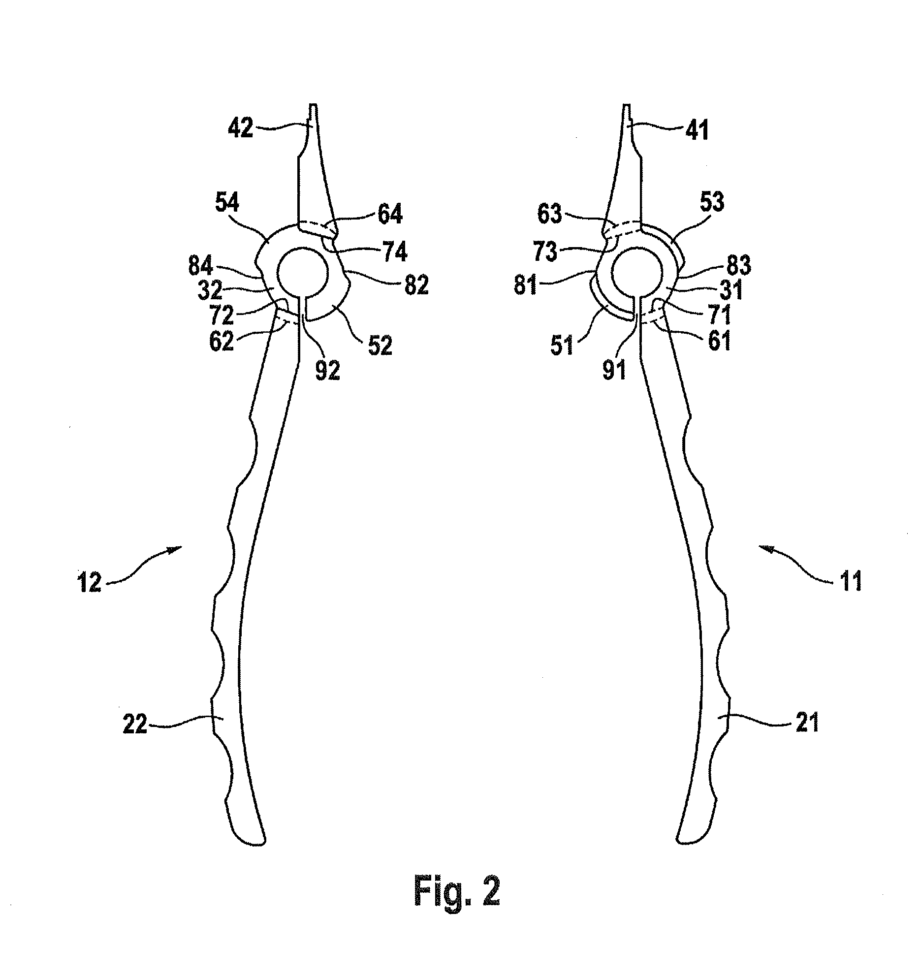
[0028]The exemplary embodiment of the surgical forceps according to the figures includes a handle 2, a pivot joint 3, a jaw 4 and a first and a second forceps part 11, 12. The first forceps part 11 includes a first control element 21, a first pivot joint element 31 and a first jaw element 41. In the coupled state, when the first forceps part 11 is coupled with a second forceps part 12, a force can be transmitted via the first control element 21 and a second control element 22, which is arranged on the second forceps part 12, by means of the first pivot joint element 31 and a second pivot joint element 32 onto the first jaw element 41 and a second jaw element 42. The first and the second jaw elements 41, 42 can be developed either as scissor blades or as forceps jaws. The first pivot joint element 31 has a first guide rail 51 as well as a first thickening element 81. In one embodiment, the first thickening element 81 can be arranged on the guide rail 51 and in another embodiment it c...


PUM


Abstract

A pair of surgical forceps which can be taken apart and which includes a handle, a pivot joint with a rotational axis and a jaw. It further includes two releasably coupled forceps parts, each of which has a pin-less pivot joint element. The first pivot joint element has a first guide rail and a first guide recess. The second pivot joint element has a second guide rail and a second guide recess. The guide rails, which engage in an undercut of the guide recesses on the pivot joint elements, form a sliding guide for the pivot joint. The first pivot joint element has a first thickening element and the second pivot joint element has a second surface element. In a safety position the first thickening element interacts with the second surface element by means of clamping.

Description

REFERENCE TO RELATED APPLICATIONS[0001]This application is a national stage application under 35 USC 371 of International Application No. PCT / EP2012 / 057189, filed Apr. 19, 2012, the entire contents of which are incorporated herein by reference.FIELD OF THE INVENTION[0002]The invention relates to a pair of surgical forceps which can be taken apart and which has a pivot joint element with a thickening element.BACKGROUND OF THE INVENTION[0003]Tools with a gripping or cutting function such as, for example, scissors or forceps are used in many areas. As a rule, said tools consist of two parts which are connected together by means of a screw. If said two parts need to be cleaned, which among other things is necessary in medical application, the screw has to be undone. In addition, the surgical instrument has to meet the demands of the operation. The instrument, in particular surgical forceps, has to be sturdy, functional and easy to handle. In addition, it should have a resilient end posi...

Claims


Application Information

Patent Timeline
IPC IPC(8): A61B17/28
CPCA61B17/2816A61B2017/00836A61B2090/0813A61B17/2833
Inventor BARTELS, CAROLINDMUSCHEWSKY, KLAUS
Owner WALDEMAR LINK GMBH & CO
Why Eureka
Try Eureka