Golf club

a golf club and wood-type technology, applied in golf clubs, golf, sport apparatus, etc., can solve the problems of unstable swing plane, difficulty in catching balls at predetermined positions, and disruption of the realization of a stable swing plan

Inactive Publication Date: 2008-11-11
DAIWA SEIKO CORPORATION
View PDF8 Cites 12 Cited by
  • Summary
  • Abstract
  • Description
  • Claims
  • Application Information

AI Technical Summary

Benefits of technology

[0015]The invention is made in view of the problem that has been discussed above, and an object thereof is to provide a golf club which can realize the stabilization of the swing plane from setup or address to impact position to thereby attain a stable blow of a ball at the time of impact.
[0018]According to the golf clubs having the heads that are configured as has been described above, since the portion where the weight is concentrated (including a portion that is molded integrally with the outer shell member or a portion that is attached to the outer shell member as a weight which is a heavy member) has the directionality in which the relevant portion rises from the heel side to the toe side, the distances from the swing axis along the longitudinal direction of the shaft to the positions where the weights exist can be set so as to be substantially equal as much as possible over the direction in which the weights are concentrated or so as to have a tendency that the distances become equal to each other. As a result, as shown in FIG. 3B, centrifugal forces F1, F2, F3 which are exerted, respectively, on the head portion at a position P1 on a toe side, a position P2 at a central portion and a position P3 on a heel side can be made to become substantially equal in magnitude or tend to do so. Consequently, since the centrifugal forces exerted on the head at the respective positions are stabilized, the exertion of an unnatural force like those shown in FIGS. 3A and 4 on the distal end side of the head can be prevented during downswing, thereby making it possible to hit a ball in a stable swing plane that thereby results from the start of a downswing to the impact point of the ball. Then, since the ball can be hit in the stable swing plane, the ball can easily be caught at the sweet spot of the head, whereby the directionality of the ball so hit can be stabilized and an increase in distance can be realized.

Problems solved by technology

In other words, unless the swing plane in the downswing to the impact point of the ball is stabilized, it becomes difficult to catch the ball at the predetermined position.
Incidentally, when an unnatural force is applied during a swing to the impact point of the ball, there is caused a problem that the swing plane becomes unstable.
Namely, the realization of a stable swing plane is disrupted by the fact that the distal end side of the head is so pulled.
In addition, since a component in a horizontal direction Y of the centrifugal force attempts to pull the head in a direction indicated by an arrow D1 in FIG. 4, this component also constitutes a factor that disrupts the stable swing plane.
Then, this component in the horizontal direction Y shows a strong tendency that the head is likely to travel on an in-to-out path S1 relative to a target line T at the time of impact and hence comes to disrupt the implementation of a stable impact (ideally, while it is good to impact the ball on an in-to-in path S relative to the target line T, in the event that a force exerted on the heel side becomes too large on the contrary, there is increasing a tendency that the head travels on an out-to-in path S2, and hence this comes to disrupt the implementation of a stable impact).
However, golf players who have no such technique tend to strike the ball along an unstable swing plane that is caused by the change in the centrifugal force or strike the ball along a swing plane that has not yet be rectified or stabilized sufficiently.
In addition, even with general heads of golf clubs in which the heavy material described above is not provided, when compared with other heads having outer shell constructions, since the sole portion of the head is formed thick along the horizontal direction, its weight distribution resembles that of the heavy material M1 shown in FIGS. 3A and 3B in which weight is distributed to extend horizontally in the toe-to-heel direction, this causing a factor which disrupts the stable swing plane at the time of downswing.

Method used


Image

  • Golf club
  • Golf club
  • Golf club

Examples


first embodiment

[0039]FIGS. 5 to 10 are drawings which show a golf club according to the invention, in which FIG. 5 is a front view of the golf club, FIG. 6 is an enlarged view of a head portion, FIG. 7 is a plan view which shows a partially cutaway crown portion of the head portion, FIG. 8 shows the head portion as seen from a back portion side thereof, FIG. 9 is a sectional view taken along the line A-A in FIG. 7, and FIG. 10 is a sectional view taken along the line B-B in FIG. 7.

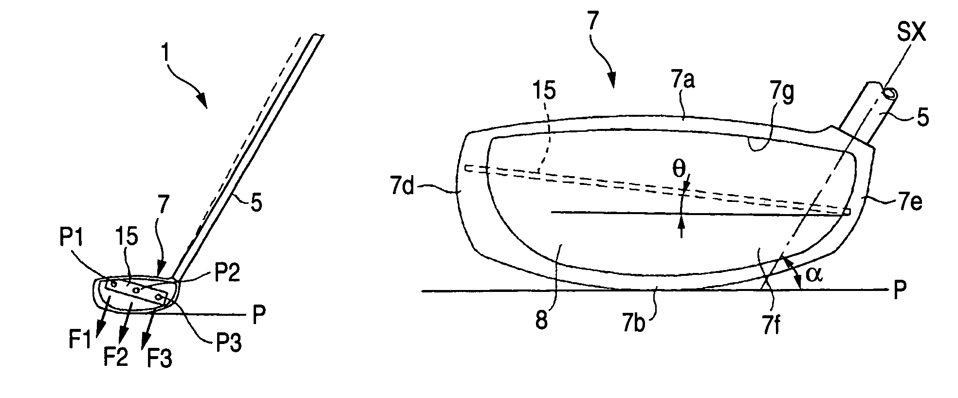
[0040]A golf club 1 according to the embodiment includes a head 7 with a hollow outer shell construction that is securely fastened to a distal end of a shaft 5 and which is made up of a crown portion 7a, a sole portion 7b, a back portion 7c, a toe portion 7d, a heal portion 7e and a face portion 7f which hits a ball. In this case, in the head 7 of the embodiment, a substantially rectangular opening 7g is formed in the face portion 7f, and a face member 8 is securely fastened in the opening 7g so formed by virtue of fusio...

second embodiment

[0057]FIGS. 14 to 18 show the invention, in which FIG. 14 is a front view of a head that is to be mounted on a shaft, FIG. 15 is a plan view which shows a partially cutaway crown portion of a head portion, FIG. 16 is a sectional view taken along the line D-D in FIG. 15, FIG. 17 is a sectional view taken along the line C-C in FIG. 14, and FIG. 18 shows the head portion as seen from a back portion side thereof.

[0058]This embodiment is configured so as to be suitably applied to a wood-type golf club for use from the fairway, and a weight concentrated portion is placed such that the position of center of gravity becomes as low as possible in consideration of an easy drive that soars into the air. Namely, this embodiment is configured so as not only to obtain the advantage obtained by the first embodiment but also to make the center of gravity of the head as low as possible.

[0059]To be specific, a weight concentrated portion 25 is formed between a face portion and a back portion of an ou...


PUM


Abstract

A golf club of the invention has a head with a hollow outer shell construction which includes a crown portion, a sole portion, a back portion, a toe portion, a heel portion and a face portion which hits a ball and a shaft that is to be mounted on the head at a predetermined lie angle, wherein a weight concentrated portion is provided closer to a back portion side than to an axis of the shaft in the interior of the head in such a manner as to rise from a heel side to a toe side of the head with respect to a reference horizontal plane which regulates the lie angle.

Description

BACKGROUND OF THE INVENTION[0001]The present invention relates to a golf club and more particularly to a wood-type golf club including a head with a hollow outer shell construction.[0002]Generally, there are known golf clubs in which a heavy material is disposed in the interior of a head thereof so as to improve the directionality of a ball hit thereby. For example, there is disclosed in Patent Document No. 1 a golf club in which a heavy material is disposed on a back side of a head in such a manner as to extend in a toe-to-heel direction. According to a head like this, the center of gravity is not concentrated to a central area of a face but extends in the toe-to-heel direction, whereby an effect can be obtained that the directionality is still stabilized even in case a ball is hit by the head at a position which is offset slightly towards the toe or heel.[0003]Patent Document No. 1: JP-A-60-153885[0004]As shown in FIG. 1, a swing that is performed by a normal golf player shares th...

Claims


Application Information

Patent Timeline
Patent Type & Authority Patents(United States)
IPC IPC(8): A63B53/04A63B53/06A63B102/32
CPCA63B53/0466A63B2053/045A63B2053/0416A63B60/00A63B53/045A63B53/0416
Inventor KUSUMOTO, HARUNOBU
Owner DAIWA SEIKO CORPORATION
Why Eureka
Try Eureka