Signal transmission apparatus and method for optical base station

a technology of optical base stations and transmission apparatuses, applied in the field of communications, can solve problems such as failure to communicate with terminals, degrade reception signals, and fail to solve problems

Inactive Publication Date: 2008-11-11
LG ERICSSON
View PDF2 Cites 133 Cited by
  • Summary
  • Abstract
  • Description
  • Claims
  • Application Information

AI Technical Summary

Benefits of technology

[0025]An object of the invention is to solve at least the above problems a...

Problems solved by technology

However, in view of the characteristics of the radio wave, shadow areas may exist, causing a failure to communicate with a terminal.
Likewise, the apparatus of FIG. 3 solves the proble...

Method used


Image

  • Signal transmission apparatus and method for optical base station
  • Signal transmission apparatus and method for optical base station
  • Signal transmission apparatus and method for optical base station

Examples


Embodiment Construction

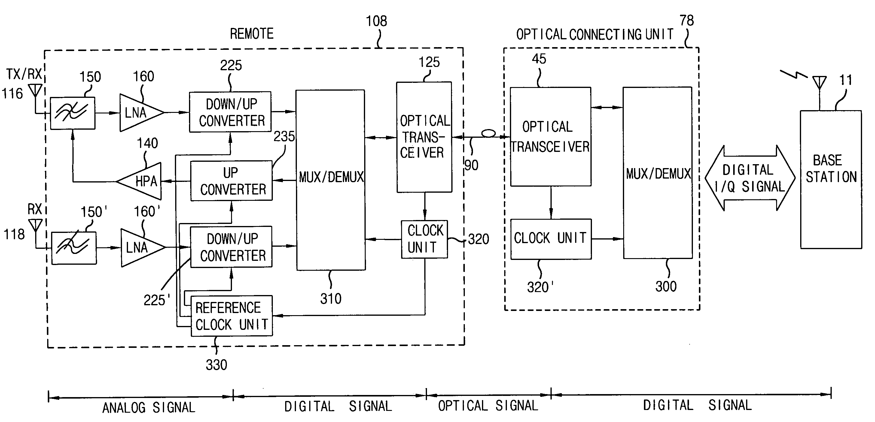
[0043]FIG. 5 is a drawing illustrating a signal transmitting apparatus for an optical base station in accordance with a preferred embodiment of the present invention, and FIG. 6 is a drawing illustrating additional details of a signal transmitting apparatus for the optical base station of FIG. 5.

[0044]As shown in FIGS. 5 and 6, a signal transmitting apparatus for an optical base station of the present invention preferably includes a base station 11 to output a digital I / Q signal and an optical connecting unit 78 to convert the digital in-phase / quadrature phase (I / Q) signal outputted from the base station 10 into an optical signal and outputting the optical signal through an optical cable 90. The system preferably may also include a remote station 108 converting the optical signal received through the optical cable 90 into a digital I / Q signal, converting the converted digital I / Q signal into a high power RF signal, and transmitting the high power RF signal to an antenna 116.

[0045]Th...


PUM


Abstract

A signal transmitting apparatus for an optical base station is disclosed. According to the invention, a base station outputs a digital IQ signal to an optical connecting unit. The optical connecting unit processes the digital IQ signal digitally, and transmits the digital signal over an optical network to a remotely located optical base station. The remote station digitally processes the signal before converting to an RF signal for transmission. The invention advantageously decreases signal loss and noise associated with analog processing in the optical connecting units and remote stations in the related art. System reliability is also improved.

Description

BACKGROUND OF THE INVENTION[0001]1. Field of the Invention[0002]The present invention relates to a base station for communications, and more particularly, to a base station using optical communications.[0003]2. Background of the Related Art[0004]FIG. 1 is a conceptual view of a general optical base station. As shown therein, a mobile communication base station 10 transmits a radio signal with sufficient power to reach to every terminal within a service area. However, in view of the characteristics of the radio wave, shadow areas may exist, causing a failure to communicate with a terminal. Shadow areas may be the result of a skyscraper, a rear side of hill areas, or an underground living area. In addition, if a new skyscraper is built, a new shadow area is generated.[0005]In order to provide the shadow area with a communication service, a communication service provider should establish a new base station or operate a small-sized remote base station 100 using the same frequency, data ...

Claims


Application Information

Patent Timeline
IPC IPC(8): H04B10/00H04B10/2575
CPCH04B10/25753H04B10/25759H04B10/29
Inventor KIM, WOO SIKKIM, YOENG KI
Owner LG ERICSSON
Why Eureka
Try Eureka