Method and apparatus for measuring particle motion using scattered radiation

a technology of scattered radiation and particle motion, which is applied in the direction of reradiation, instruments, devices using optical means, etc., can solve the problems of multiple lasers, multiple detectors and multiple detectors, and the inability of a detection system to resolve the scattered light arising from one radiation source, etc., and achieve the effect of wide scattered signal bandwidth and short period of tim

Inactive Publication Date: 2008-11-18
NORTHBY JAN ARWOOD
View PDF11 Cites 1 Cited by
  • Summary
  • Abstract
  • Description
  • Claims
  • Application Information

AI Technical Summary

Benefits of technology

[0008]The invention uses adjacent spatial regions that are not optically resolved and, indeed, can even intersect. The invention utilizes all identical and inexpensive light sources, involves only a single detector, and is straightforward to generalize to higher dimensions. It does not involve coherent light and therefore is less susceptible to window degradation and isotropic scattering in the medium. The invention also shifts the complexity from relatively expensive optics, to relatively inexpensive electronics. The invention has the further advantage that under many situations, it can simultaneously provide detailed information about the particle size distribution, as well the particle velocity distribution, in a flow.
[0018]In one embodiment, the beam modulation can be set at very high frequency so that the modulation and beat frequencies can be removed while still leaving a wide scattered signal bandwidth. As a result, velocity measurements can be made in a short period of time, as long as the particle density is high enough so that one or more particles will cross both beams during that period.
[0019]In another aspect, it is possible to move the beam pattern, using mirrors or other suitable mechanisms, from one point to another and obtain stationary beam measurements at several points in a short period of time. This allows for the measurement of both the velocity and various velocity derivatives. In one relative motion based detection apparatus, it is possible to raster a beam pattern and measure relative velocity over a region of space. The properties of particles at rest can also be measured using this method.

Problems solved by technology

Therefore, it is often difficult for a detection system to resolve the scattered light arising from one radiation source from the scattered light arising from another source.
The primary problems associated with using different wavelengths are that multiple detectors and multiple lasers are used.
The laser may have distinct properties, including power, size, emitting area, and / or emission patterns, which complicates calibration of the individual detectors, and compromises accuracy.
While it is possible to use these instruments in situ with naturally occurring particles, it is not convenient.
For example, since one requires coherence of the two beams, a slight change in the optical path associated with window degradation or a discontinuity in the medium can distort the fringe pattern.
Furthermore, the naturally available particle distribution may not be suitable, for example, too many particles or the wrong size particle.
Finally, since coherent beams require high quality lasers, the devices are relatively expensive.

Method used


Image

  • Method and apparatus for measuring particle motion using scattered radiation
  • Method and apparatus for measuring particle motion using scattered radiation
  • Method and apparatus for measuring particle motion using scattered radiation

Examples


Embodiment Construction

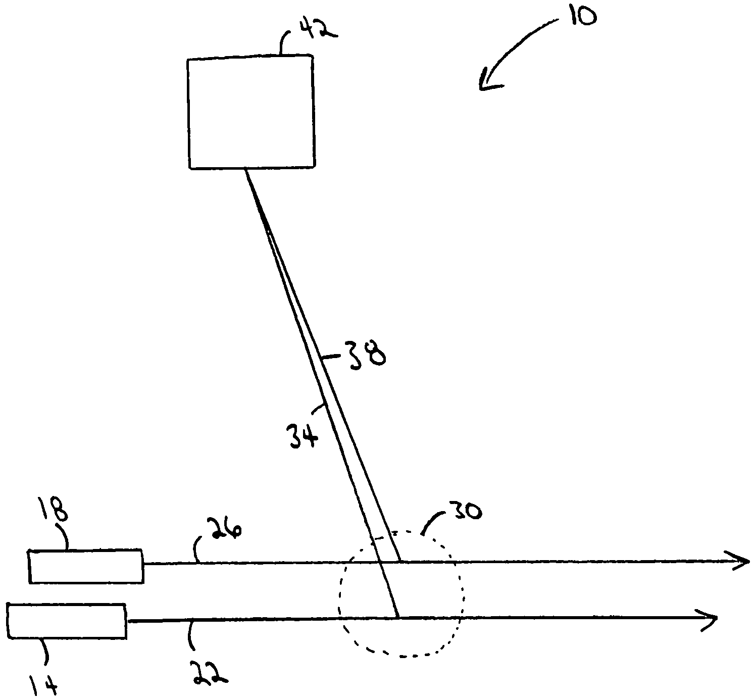
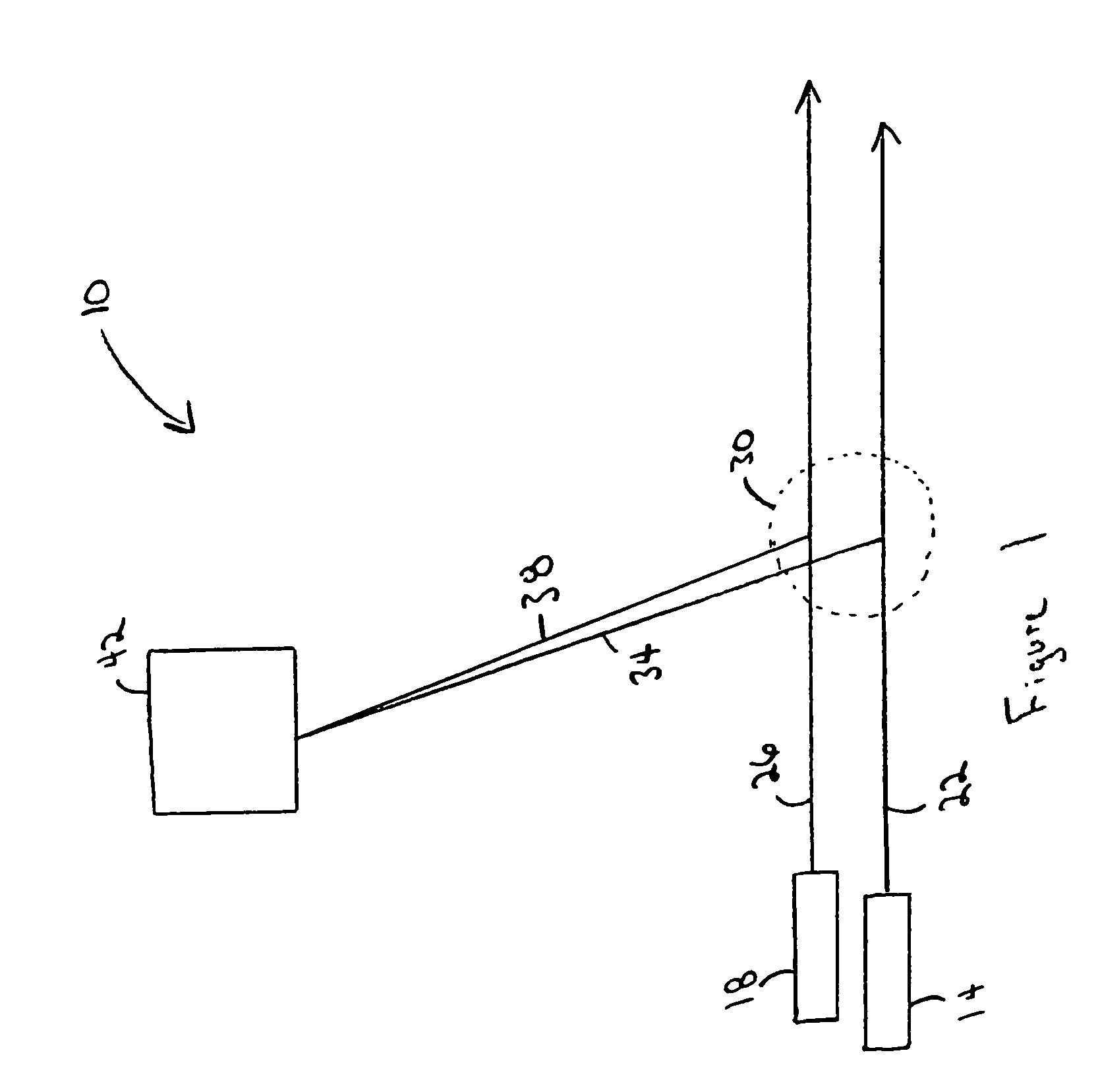
[0040]FIG. 1 depicts an embodiment of an apparatus 10 for measuring particle motion. The apparatus 10, in use, includes a first source of radiation 14, a second source of radiation 18, a first beam of radiation 22 generated by the first source of radiation 14, a second beam of radiation 26 generated by the second source of radiation 18, an observation region 30 in which particles scatter radiation, a first beam of scattered radiation 34, a second beam of scattered radiation 38, and a detector 42. The two sources 14 and 18 project the two beams of radiation 22 and 26, respectively, in a first direction through a transparent medium. The two beams 22 and 26 are intersected by a particle (not shown) traveling in a second direction. As the particle crosses the first beam of radiation 22 in the observation region 30, it scatters radiation and forms the first beam of scattered radiation 34, which is received by the detector 42. As the particle crosses the second beam of radiation 26 in the...


PUM

PropertyMeasurementUnit
frequencyaaaaaaaaaa
frequencyaaaaaaaaaa
wavelengthaaaaaaaaaa

Abstract

A method and apparatus for measuring particle motion using electromagnetic radiation uses beams of radiation modulated with a distinct frequency and / or phase. A particle traversing these beams scatters a portion of the radiation. Scattered radiation, which retains its modulation information, is then detected, and a cross-correlation technique is used to quantify the particle's motion, for example, particle velocity.

Description

CROSS-REFERENCE TO RELATED APPLICATION[0001]This application claims the benefits of and priority to U.S. Provisional Patent Application Ser. No. 60 / 399,974 filed on Jul. 31, 2002 and to U.S. patent application Ser. No. 10 / 632,180 filed on Jul. 31, 2003, the disclosures of which are incorporated herein by reference in their entirety.FIELD OF THE INVENTION[0002]The invention relates generally to the field of methods and apparatus for measuring particle motion, and more particularly to measuring particle motion using scattered light.BACKGROUND OF THE INVENTION[0003]Quantitative information about a material in a region of space may be obtained remotely by observing how the material scatters radiation projected through that region. The scattering process normally causes the light to be reemitted diffusely in all directions though. Therefore, it is often difficult for a detection system to resolve the scattered light arising from one radiation source from the scattered light arising from ...

Claims


Application Information

Patent Timeline
Patent Type & Authority Patents(United States)
IPC IPC(8): G01N21/00G01P3/36G01P5/20G01P5/22G01S7/4912G01S17/58G01S17/87
CPCG01P5/20G01P5/22G01S17/58G01S7/4912G01S17/87
Inventor NORTHBY, JAN ARWOOD
Owner NORTHBY JAN ARWOOD
Why Eureka
Try Eureka