Tape measure

a tape measure and tape technology, applied in the field of tape measures, can solve the problems of excessive ovalization of tape, damage to the tang, deterioration of the accuracy of measurement, etc., and achieve the effect of reducing operator errors

Inactive Publication Date: 2008-11-25
WISE ROBERT W
View PDF41 Cites 23 Cited by
  • Summary
  • Abstract
  • Description
  • Claims
  • Application Information

AI Technical Summary

Benefits of technology

[0007]It is therefore yet another objective of the present invention to provide tape of a tape measure that permits a practitioner to “burn an inch” when taking measurements without having to remember that the inch was burned.
[0008]It is therefore still yet another objective of the present invention to provide a clip fixedly attached to a tape of a tape measure that permits a practitioner to obtain more accurate measurements compared to measurements taken from a conventional floating clip.
[0010]As will be readily appreciated from the foregoing summary, the invention provides a tape measure having markings that operate with an end clip and an intermediate clip to provide various ways of taking linear measurements. More specifically, the end clip is configured to provide accurate measurements reduce operator error when a practitioner desires to burn an inch.

Problems solved by technology

One drawback of such conventional tape measures is that the tang can become damaged or bent.
Another drawback is that the rivet holes in the tape may become excessively ovalized, especially after repeated usage, and the accuracy of the measurement deteriorates.
This is generally not a problem for measurements with tolerances of ±⅛″, but may be a problem for measurements requiring greater accuracy, e.g., ± 1 / 16″).
One error that may occur, however, is that the practitioner forgets about the “one inch” that was burned and ends up one inch short when subsequently cutting material.

Method used


Image

  • Tape measure
  • Tape measure
  • Tape measure

Examples


Embodiment Construction

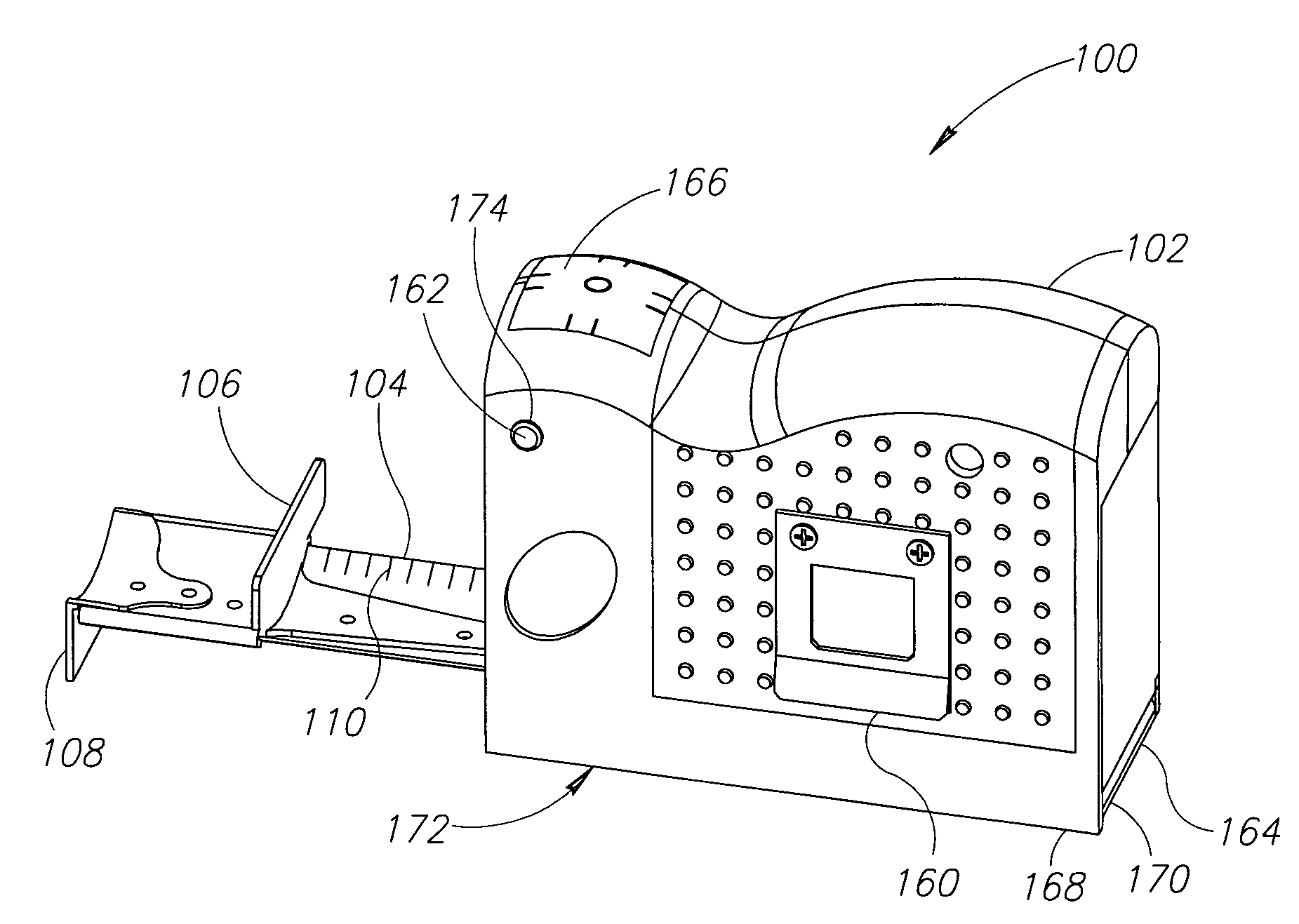
[0020]In general, a retractable tape measure includes a retractable tape in a housing, which includes a mechanism for retracting the tape through a housing opening. The tape measure also includes an end stop for preventing the free end of the tape from retracting into the housing and a lock mechanism to lock the tape in an extended position. The tape itself typical includes indicia or markings along the surface of the tape that will be viewed by a practitioner using the tape. In order to provide bending stiffness to the tape, the tape is usually manufactured with a lateral cross-section curvature in which the edges of the tape are turned upward. In the various figures of the attached drawings, the numbered elements in the figures correspond to like numbered elements herein.

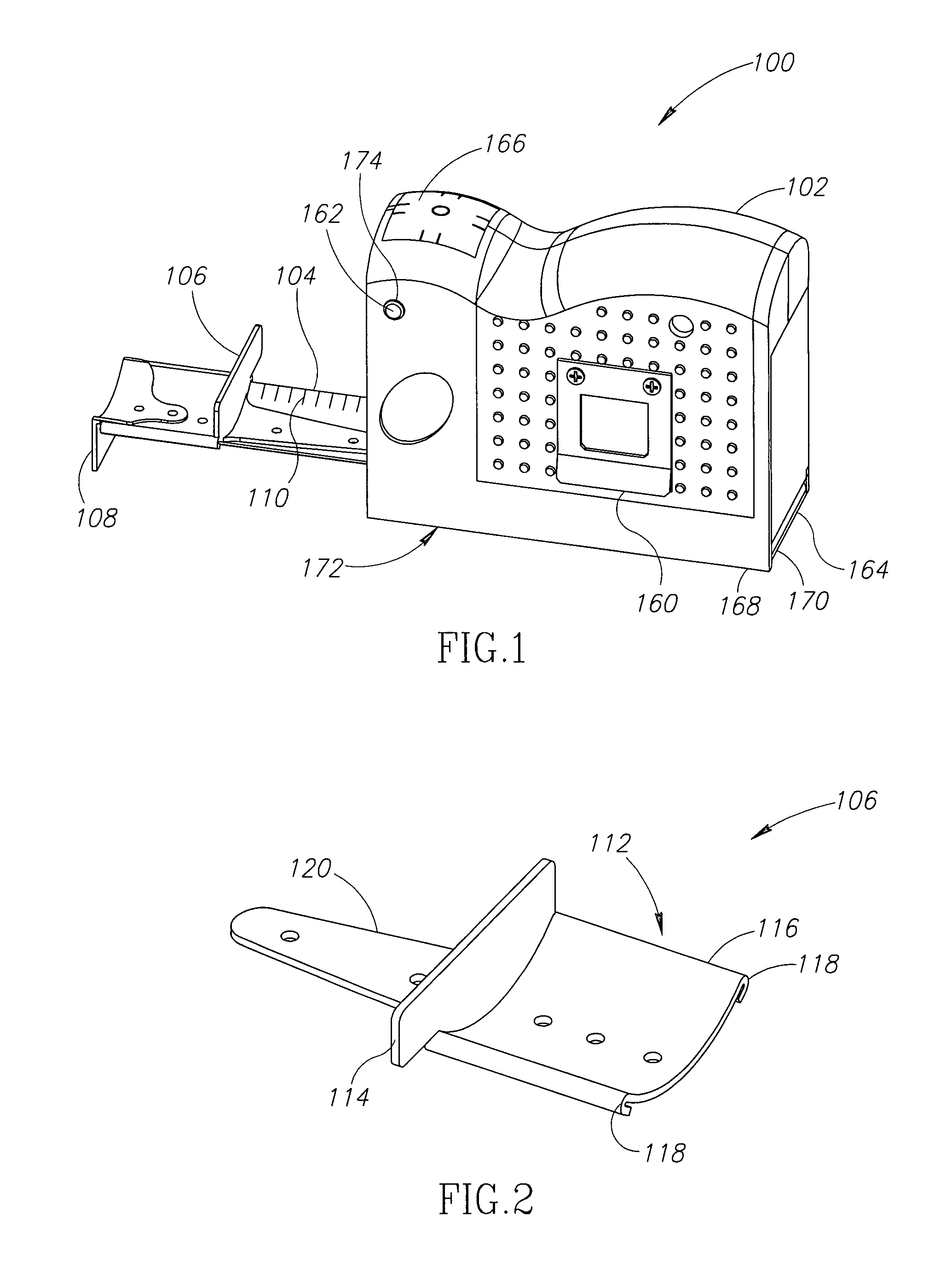
[0021]FIG. 1 shows a tape measure 100 having a housing 102 and a tape 104 with fixed, intermediate clip 106 and floating end clip 108 attached thereto. In addition, the tape 104 includes indicia or markings 110 fo...


PUM


Abstract

A tape measure includes a housing and a tape retractably coupled to the housing. The tape has an upper surface, a lower surface, and a free end onto which an end clip is moveably coupled. The end clip includes a first attachment portion and a first flange extending therefrom. In addition, an intermediate clip is fixedly coupled to the tape. The intermediate clip includes a second attachment portion and a second flange extending from second attachment portion. The second flange includes a flange face located one measurement unit from the free end of the tape. The end clip cooperates with a set of first measurement markings applied to the tape to provide linear measurements. Whereas, the intermediate clip cooperates with a set of second measurement markings applied to the tape. The set of second measurements markings commence at one measurement unit from the free end of the tape. In addition, the tape measure may include reverse marking applied to the back side of the tape. The reverse measurement markings cooperate with the intermediate clip and can be used in specialty trades.

Description

FIELD OF THE INVENTION[0001]This invention relates generally to tape measures configured to provide at least two different methods of taking measurements. More specifically, the invention relates to tape measures having two different origins for mensurations.BACKGROUND OF THE INVENTION[0002]Tape measures are used for a variety of purposes. One conventional type of a tape measure is designed for carpentry or construction and employs a resilient, curved metallic tape that can remain stiff and straight when extended, but retracts into a coil for convenient storage into a handheld housing. The tape of the tape measure includes markings for linear measurements. These conventional tape measures have a floating tang or clip on the end of the tape to aid measuring. The tang is typically attached to the end of the tape with rivets received in ovalized holes in the tape so as to permit the tang to float a distance equal to its thickness. This floating attachment allows for a fairly accurate m...

Claims


Application Information

Patent Timeline
Patent Type & Authority Patents(United States)
IPC IPC(8): G01B3/10
CPCG01B3/1056G01B3/1082G01B3/1003
Inventor WISE, ROBERT W.
Owner WISE ROBERT W
Why Eureka
Try Eureka