Trigger forward pivot limit for a trigger sprayer

a technology of forward pivot limit and trigger sprayer, which is applied in the direction of instruments, liquid transfer devices, single-unit apparatuses, etc., to achieve the effect of preventing further forward movement of the trigger

Active Publication Date: 2008-11-25
WESTROCK DISPENSING SYST
View PDF15 Cites 22 Cited by
  • Summary
  • Abstract
  • Description
  • Claims
  • Application Information

AI Technical Summary

Benefits of technology

[0016]The trigger sprayer of the present invention overcomes the potential problems caused by the trigger contacting the nozzle assembly of the trigger sprayer by providing features in the construction of the trigger sprayer that limit the forward movement of the trigger and thereby prevent the trigger from engaging with the nozzle assembly. In this way, the construction of the trigger sprayer of the invention prevents the unintended and undesirable separation of the nozzle assembly from the sprayer housing.
[0027]The trigger also includes a pair of tabs that project in the axial direction from the pivot posts. The pair of tabs are positioned on the trigger where the tabs engage against the stop surfaces of the sprayer housing when the trigger is moved forwardly toward the discharge position of the trigger relative to the sprayer housing, and thereby prevent further forward movement of the trigger. The pair of tabs move in an arc movement away from the stop surfaces of the sprayer housing when the trigger is moved from the charge position of the trigger to the discharge position of the trigger relative to the sprayer housing. The pair of tabs on the trigger and the pair of stop surfaces on the sprayer housing thereby limit the extent of forward movement of the trigger relative to the sprayer housing and prevent the trigger from moving forwardly and engaging with the nozzle assembly and potentially dislodging the nozzle assembly from the sprayer housing.

Problems solved by technology

This would result in the engagement of the trigger against the portion of the nozzle assembly dislodging and pushing the nozzle assembly off of the liquid discharge opening of the sprayer housing.

Method used


Image

  • Trigger forward pivot limit for a trigger sprayer
  • Trigger forward pivot limit for a trigger sprayer
  • Trigger forward pivot limit for a trigger sprayer

Examples


Embodiment Construction

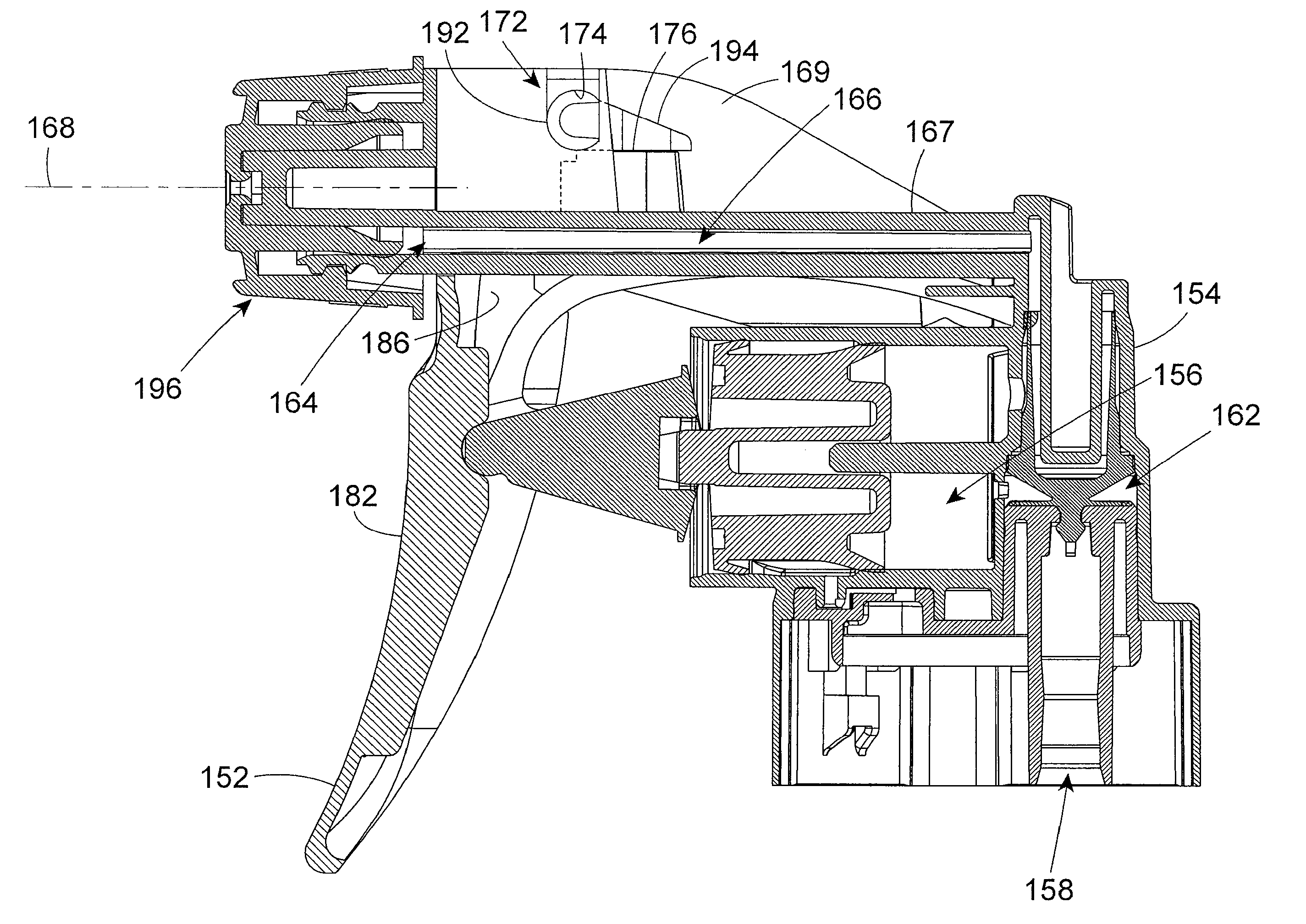
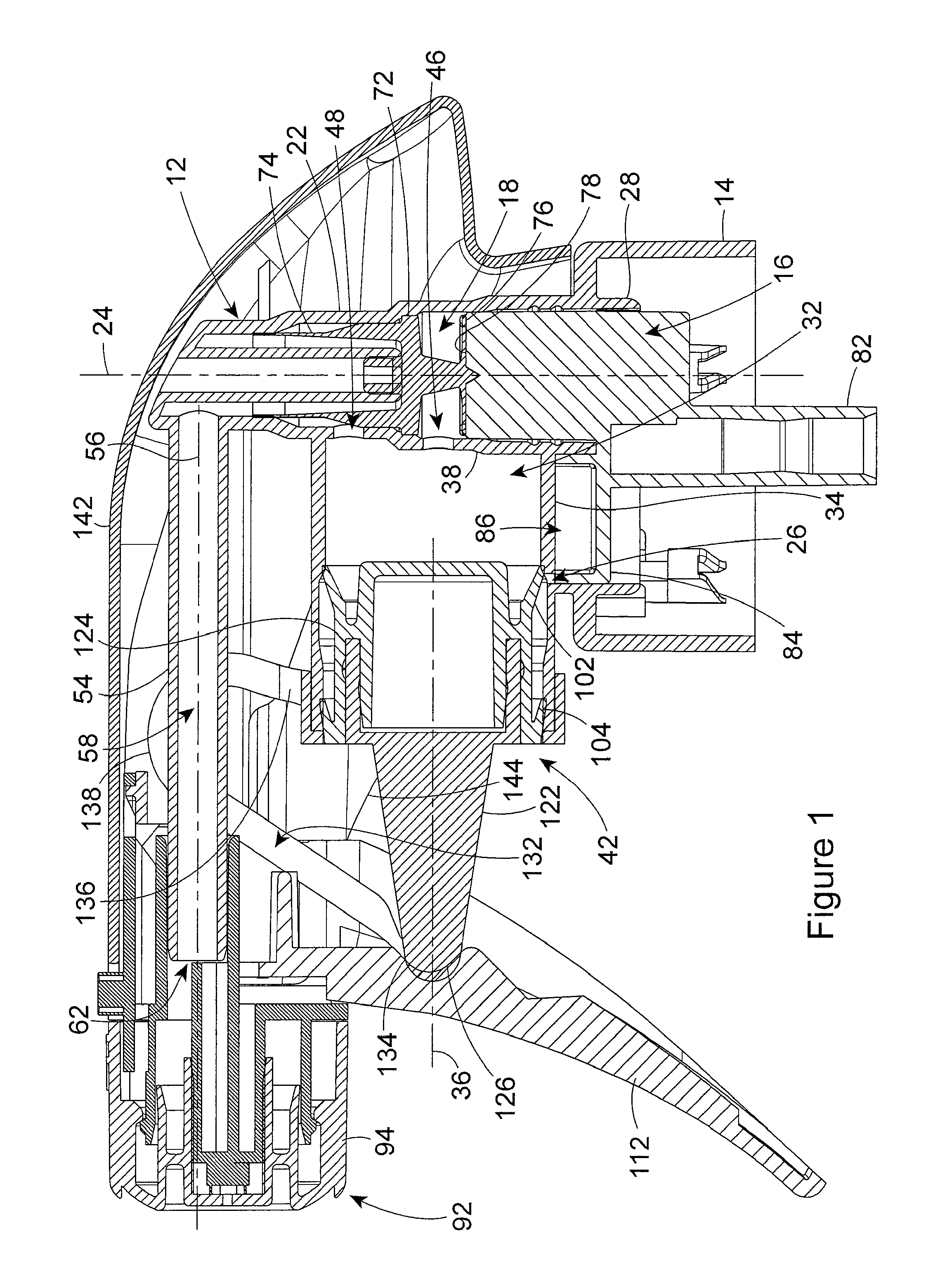
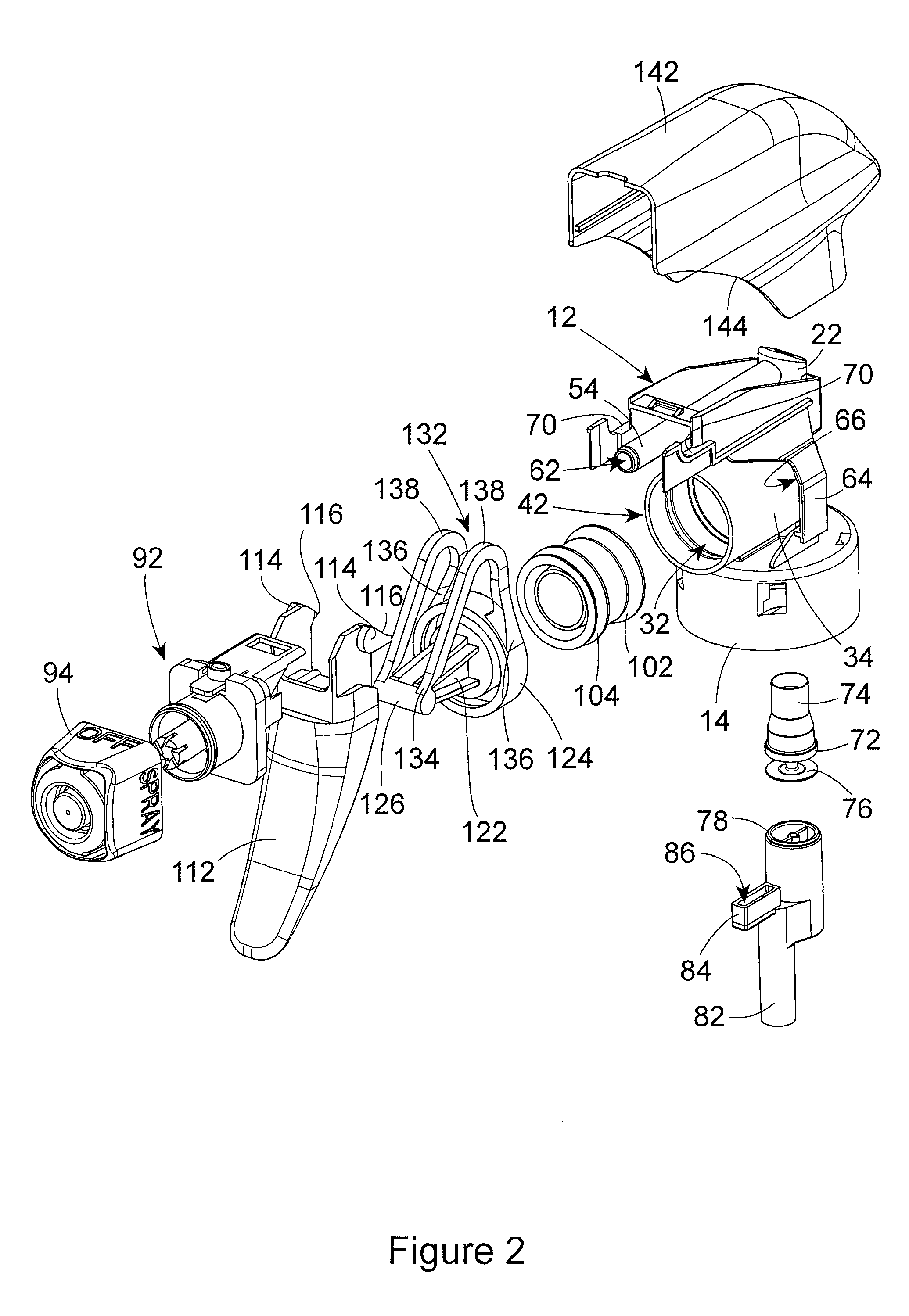
[0045]Several component parts of the trigger sprayer of the invention are found in the typical construction of a trigger sprayer, and therefore these component parts are described only generally herein. It should be understood that although the component parts are shown in the drawing figures and are described as having a certain construction, other equivalent constructions of the component parts are known. These other equivalent constructions of trigger sprayer component parts are equally well suited for use with the novel features of the invention to be described herein.

[0046]The trigger sprayer includes a sprayer housing 12 that is formed integrally with a connector cap 14. The connector cap 14 removably attaches the trigger sprayer to the neck of a bottle containing the liquid to be dispensed by the trigger sprayer. The connector cap 14 shown in the drawing figures has a bayonet-type connector on its interior. Other types of equivalent connectors may be employed in attaching the...


PUM


Abstract

A manually operated trigger sprayer includes a feature that limits the forward pivoting movement of the trigger. By limiting the forward pivoting movement of the trigger, the novel construction of the trigger sprayer prevents the trigger from engaging against the nozzle assembly attached to the sprayer housing of the trigger sprayer and potentially dislodging the nozzle assembly from its attachment to the trigger sprayer housing.

Description

[0001]This patent application is a continuation-in-part from patent application Ser. No. 11 / 369,351, which was filed on Mar. 7, 2006, and is currently pending.BACKGROUND OF THE INVENTION[0002](1) Field of the Invention[0003]The present invention pertains to the construction of a manually operated trigger sprayer that includes a feature that limits the forward pivoting movement of the trigger. By limiting the forward pivoting movement of the trigger, the novel construction of the trigger sprayer prevents the trigger from engaging against the nozzle assembly attached to the sprayer housing of the trigger sprayer and potentially dislodging the nozzle assembly from its attachment to the sprayer housing.[0004](2) Description of the Related Art[0005]Handheld and hand pumped liquid dispensers commonly known as trigger sprayers are used to dispense many household products and commercial cleaners. Trigger sprayers have been used to dispense household cleaning or cooking liquids and have been...

Claims


Application Information

Patent Timeline
Patent Type & Authority Patents(United States)
IPC IPC(8): B67D5/40B67D7/58
CPCB05B11/3011B05B11/3064B05B11/3074B05B11/3077B05B11/0029B05B11/1011B05B11/1064B05B11/1074B05B11/1077
Inventor FOSTER, DONALD D.NELSON, PHILIP L.CLYNES, WALTER J.
Owner WESTROCK DISPENSING SYST
Why Eureka
Try Eureka