Magnetic fluid rotary feedthrough with sensing and communication capability

a magnetic fluid and rotary technology, applied in the field of magnetic fluid rotary feedthroughs, can solve the problems of loss of yield or complete ruination of products, slow and steady evaporation of oil, and difficult to solve the problem of dynamic rotary vacuum sealing, etc., to achieve low evaporation rate and easy identification

Inactive Publication Date: 2010-09-16
FERROTEC UK
View PDF11 Cites 12 Cited by
  • Summary
  • Abstract
  • Description
  • Claims
  • Application Information

AI Technical Summary

Benefits of technology

[0014]Magnetic fluid rotary feedthroughs are often seen as critical components in the equipment where they are used to maintain a dynamic rotary seal over extended periods of time and diverse operating conditions. Dynamic rotary vacuum sealing is a very difficult problem to solve particularly as any leak of atmospheric gases into the vacuum chamber can result in contamination of the product resulting in either loss of yield or complete ruination of the product. Consequently, magnetic fluid rotary feedthroughs have become the accepted standard and under normal operating conditions these feedthroughs are very reliable, operating successfully without servicing for many years. Indeed, it is the very reliability of these devices that leads users to assume that they will continue operating without attention indefinitely. However, it must be recognized that exposure of the magnetic fluid to a very high vacuum, particularly if the process is at a high temperature, can result in a slow and steady evaporation of the oil. The evaporation rate is mainly dependant on the level of the vacuum and the temperature, both of which tend to change over the operating life of the product. However, for high quality magnetic fluids, operating even at very high temperatures, the evaporation is at such an extremely low rate it takes place over many years. Therefore, it makes any decision of “if” and “when” to service the feedthrough particularly difficult to define.
[0016]For both of the above reasons, low evaporation rates and difficulty in defining bearing life, magnetic fluid feedthroughs are either replaced at unnecessarily short intervals or, alternatively, not replaced at all until they fail. Neither solution represents a satisfactory situation for a component often seen as having critical importance. It is advantageous to be able to monitor the condition of feedthroughs and signal their condition to operators or diagnostic equipment.
[0017]Therefore, it is an object of the present invention to provide a rotary feedthrough that is capable of indicating the condition of the rotary feedthrough. It is another object of the present invention to provide a rotary feedthrough that is capable of indicating the condition of the rotary feedthrough to enable maintenance when required of the feedthrough at a scheduled shut down. It is a further object of the present invention to provide a rotary feedthrough with a means to easily identify a potentially failing rotary feedthrough among a plurality of rotary feedthroughs. It is still another object of the present invention to provide a rotary feedthrough that is capable of providing an advanced warning of a potential problem with the rotary feedthrough. It is yet another object of the present invention to enable identification of a problem feedthrough in a degraded condition operating amongst a plurality of feedthroughs.

Problems solved by technology

Dynamic rotary vacuum sealing is a very difficult problem to solve particularly as any leak of atmospheric gases into the vacuum chamber can result in contamination of the product resulting in either loss of yield or complete ruination of the product.
However, it must be recognized that exposure of the magnetic fluid to a very high vacuum, particularly if the process is at a high temperature, can result in a slow and steady evaporation of the oil.
However, for high quality magnetic fluids, operating even at very high temperatures, the evaporation is at such an extremely low rate it takes place over many years.
Therefore, it makes any decision of “if” and “when” to service the feedthrough particularly difficult to define.
Feedthroughs, especially those operating at high speeds or high loads, are particularly demanding on the bearings.
These demands are magnified as bearing lubricants that are compatible with vacuum operation are not particularly good compared to conventional bearing lubricants.
Therefore, failure of the bearing within the vacuum environment is often observed while the bearing on the atmosphere side, often lubricated with a good quality conventional lubricant, remains in excellent condition.
There is little supporting data, however, on the demands of operating in a vacuum environment with relatively poor lubricants.
The wide variation in life over diverse operating conditions coupled with the large error band on any supporting data makes the definition of a suitable maintenance schedule very difficult.
For both of the above reasons, low evaporation rates and difficulty in defining bearing life, magnetic fluid feedthroughs are either replaced at unnecessarily short intervals or, alternatively, not replaced at all until they fail.

Method used


Image

  • Magnetic fluid rotary feedthrough with sensing and communication capability
  • Magnetic fluid rotary feedthrough with sensing and communication capability
  • Magnetic fluid rotary feedthrough with sensing and communication capability

Examples


Embodiment Construction

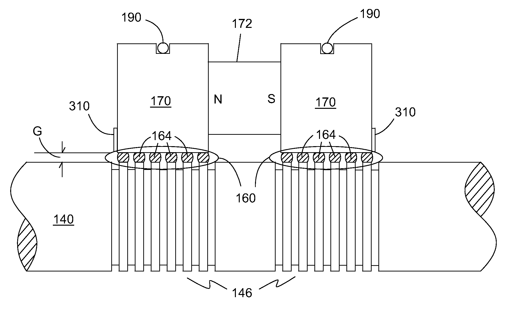
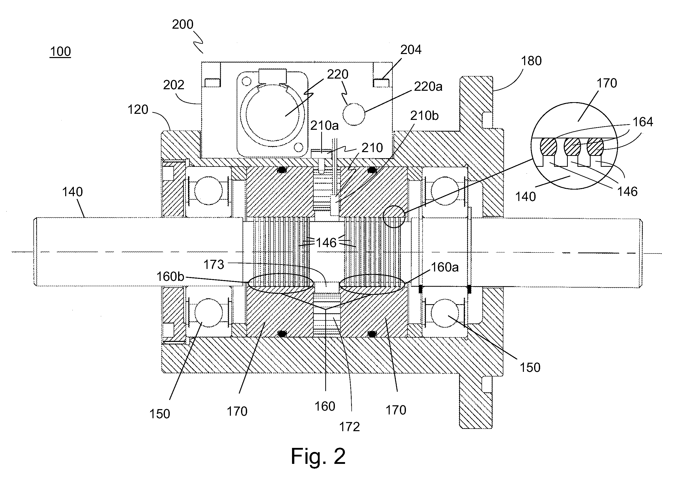
[0033]The preferred embodiment of the present invention is illustrated in FIGS. 2-3. FIG. 2 shows one embodiment of a magnetic fluid rotary feedthrough 100 of the present invention in a partial cross-sectional view. Rotary feedthrough 100 includes a feedthrough housing 120 and a rotary shaft 140 that extends out of feedthrough housing 120. Shaft 140 is magnetically permeable and has two sets of stages or teeth 146. Housing 120 includes a vacuum compatible flange 180 for mounting the rotary feedthrough 100 to a vacuum chamber. Shaft 140 is typically supported by a pair of bearings 150 that are disposed on either side of the magnetic fluid seal 160. The magnetic fluid seal 160 includes two stationary, magnetically-permeable elements 170, which are referred to as pole-pieces. Pole-pieces 170 carry magnetic flux from a permanent magnet or magnets 172, disposed between pole-pieces 170. The magnetic flux is concentrated at shaft 140 by a series of stages or teeth 146 cut into shaft 140. T...


PUM


Abstract

A magnetic fluid rotary feedthrough has a multi-stage magnetic fluid rotary seal adapted to provide a magnetic fluid seal about a shaft for extending between a first environment and a second environment, one or more sensors integrally mounted within the magnetic fluid rotary feedthrough to sense one or more physical parameters of the multi-stage magnetic fluid rotary seal, signal processing electronics mounted to or incorporated in the magnetic fluid rotary feedthrough to receive one or more sensor output signals from the one or more sensors, to process the one or more sensor output signals and to output one or more electronic processing signals, and one or more output devices operatively connected to receive the one or more electronic processing signals from the signal processing electronics to indicate the condition of the multi-stage magnetic fluid rotary seal.

Description

[0001]This application claims the benefit of U.S. Provisional Pat. App. No. 61 / 159,458, filed Mar.12, 2009.BACKGROUND OF THE INVENTION[0002]1. Field of the Invention[0003]The present invention relates generally to the field of magnetic fluid seals. Particularly, the present invention relates to a multi-stage magnetic fluid seal assembly. More particularly, the present invention relates to magnetic fluid rotary feedthroughs.[0004]2. Description of the Prior Art[0005]Magnetic fluid feedthroughs have been developed for use in vacuum systems where they perform the function of providing a virtually hermetic rotating seal. These products rely on the entrapment of magnetic fluid and its ability to withstand a pressure differential when magnetically trapped. Vacuum feedthroughs are designed to withstand low pressures on the order of 1 to 2 atmospheres and are impervious to all gases.[0006]A conventional design of a magnetic fluid feedthrough is illustrated in FIG. 1. A magnetic fluid rotary...

Claims


Application Information

Patent Timeline
Patent Type & Authority Applications(United States)
IPC IPC(8): F16J15/43G01M3/00G06F19/00G08B21/00
CPCF16J15/43
Inventor BROOKS, DOUGLAS A.LEWCOCK, JEFFREY C.JOHANSEN, DAVID
Owner FERROTEC UK
Why Eureka
Try Eureka