Coaxial cable connector with friction-fit sleeve

a technology of friction-fitting sleeves and coaxial cables, which is applied in the direction of coupling devices, two-part coupling devices, electrical devices, etc., can solve the problems of complex structural features, inability to mold complex structural features, and inability to meet the requirements of assembly, so as to improve the gripping ability of cables, simple design, and easy manufacturing of components

Active Publication Date: 2008-11-25
PPC BROADBAND INC
View PDF238 Cites 46 Cited by
  • Summary
  • Abstract
  • Description
  • Claims
  • Application Information

AI Technical Summary

Benefits of technology

[0009]It is a further object of the present invention to provide a coaxial cable connector having improved cable gripping capabilities, while utilizing simply designed and easily manufactured components.
[0010]In the efficient attainment of these and other objects, the present invention provides a coaxial cable connector. The connector of the present invention generally includes an annular post defining an axial bore therein, a cylindrical connector body coupled to the post, a nut rotatably coupled to the post and a sleeve movably connected to the connector body. The sleeve includes at least one radially outwardly extending ridge formed on an outer surface thereof, which frictionally engages an inner surface of the connector body. As a result, the inner surface of the connector body does not require a recess or other engagement structure formed thereon.
[0012]The ridges may be divided into two axially spaced forward ridges and two axially spaced rearward ridges. The forward ridges have a first diameter and the rearward ridges have a second diameter that is slightly larger than the first diameter so that a greater holding force is provided by the interference-fit upon full insertion of the sleeve into the body. A rearward-most locking ridge and an abutment surface may also be provided adjacent a flanged head portion of the sleeve to enhance locking of the sleeve into the connector body.
[0014]To further enhance gripping of the cable, the coaxial cable connector of the present invention preferably includes a connector body having a rearward sleeve receiving end, an annular post disposed within the connector body and an axially movable locking sleeve seated in the rearward sleeve receiving end of the connector body. The post has a radially outwardly projecting barb disposed at a rearward end thereof and the locking sleeve has an inwardly directed shoulder portion, which is positioned axially forward of the post barb when the sleeve is moved to a forward most locking position in the connector body.

Problems solved by technology

Two cost factors in manufacturing these connectors are the complexity and the material of the individual connector components that are required for assembly.
However, molding complex structural features, such as engagement recesses and detents, into the internal diameter of the connector body are not practical, because such features hamper the opening of the mold.
Methods to circumvent this mold limitation are also costly.

Method used


Image

  • Coaxial cable connector with friction-fit sleeve
  • Coaxial cable connector with friction-fit sleeve
  • Coaxial cable connector with friction-fit sleeve

Examples


Embodiment Construction

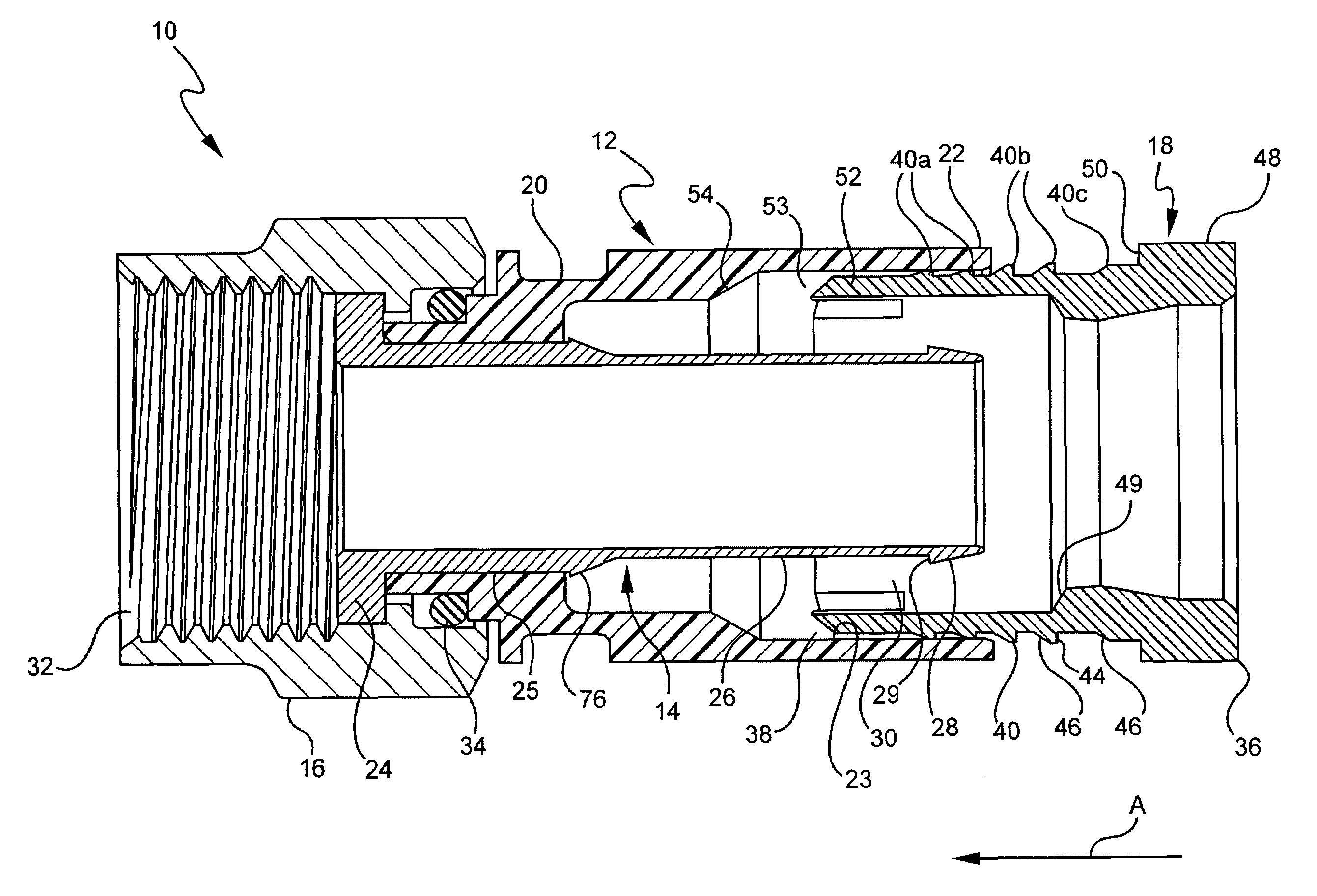
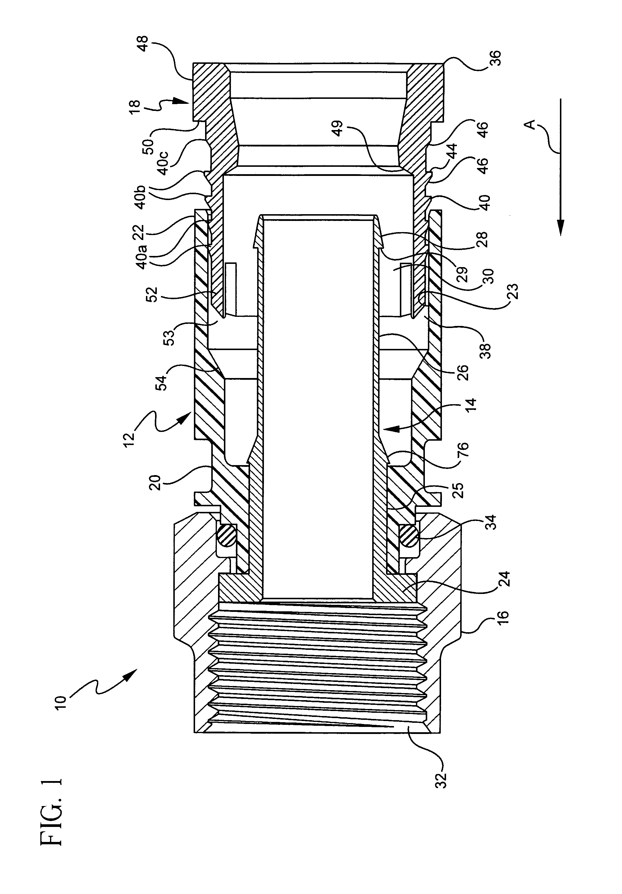
[0026]The present invention is directed to connectors for terminating coaxial cable. Coaxial connectors of this type are shown and described in commonly owned U.S. Pat. No. 6,530,807 issued Aug. 28, 2003, the disclosure of which is incorporated herein by reference.

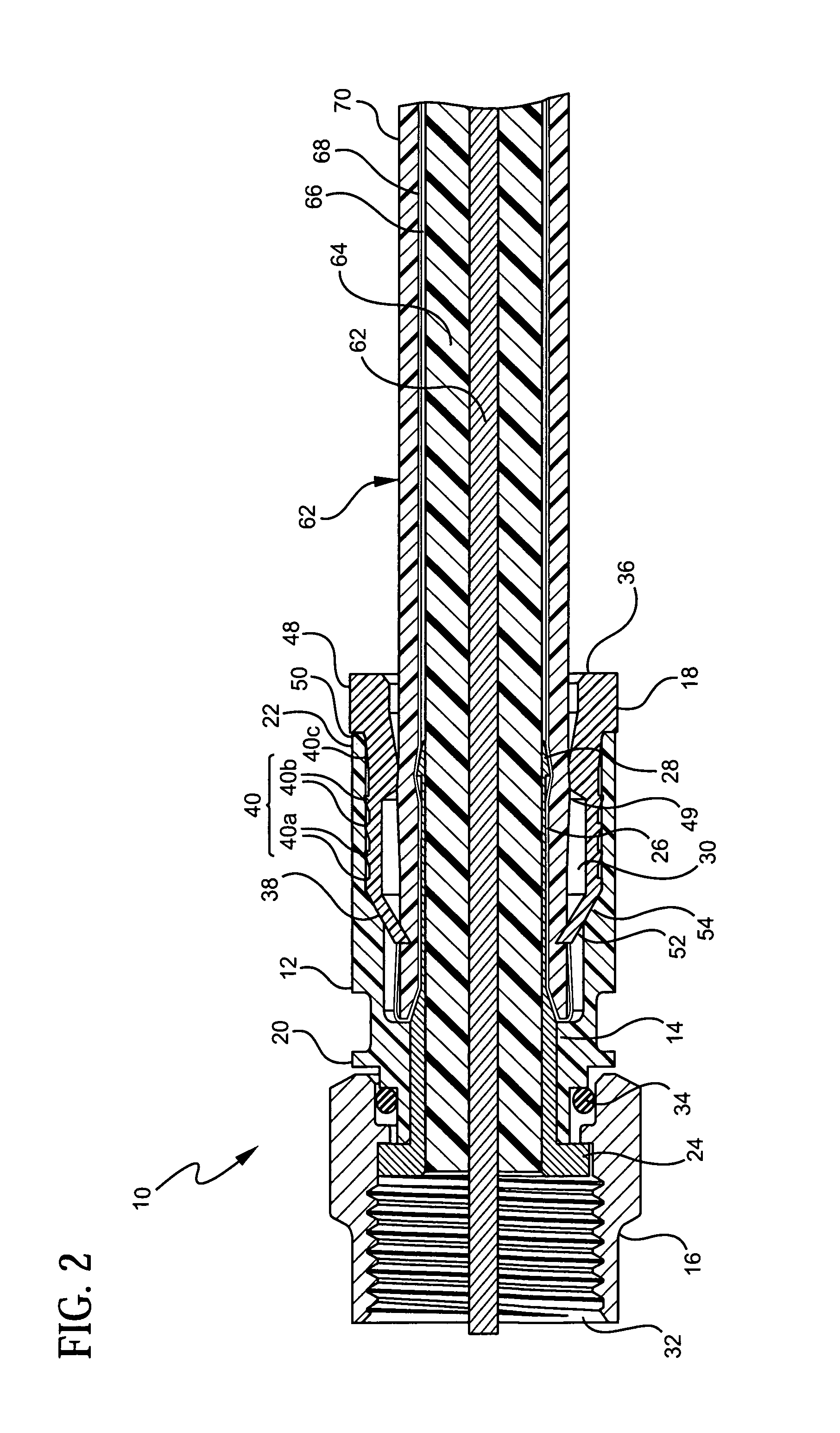
[0027]Referring to FIGS. 1 and 2, the coaxial cable connector 10 of the present invention is shown. The connector 10 generally includes four components: a connector body 12 (sometimes referred to as a “collar”); an annular post 14; a rotatable nut 16; and a movable locking sleeve 18. It is however conceivable that the connector body 12 and the post 14 can be integrated into one component and / or another fastening device other than the rotatable nut 16 can be utilized. Also, as will be discussed in further detail below, a resilient sealing O-ring 34 may be positioned between the body 12, the post 14 and the nut 16 at the rotatable juncture thereof to provide a water resistant seal thereat.

[0028]The connector body 12 is an el...


PUM


Abstract

A coaxial cable connector includes an annular post defining an axial bore therein, a cylindrical connector body coupled to the post, a nut rotatably coupled to the post and a sleeve movably connected to the connector body. The sleeve includes at least one radially outwardly extending ridge formed on an outer surface thereof, which frictionally engages an inner surface of the connector body. As a result, the inner surface of the connector body does not require a recess or other engagement structure formed thereon.

Description

CROSS-REFERENCE TO RELATED APPLICATIONS[0001]This application claims the benefit of U.S. Provisional Application No. 60 / 710,724, filed on Aug. 23, 2005 and U.S. Provisional Application No. 60 / 764,450, filed on Feb. 2, 2006.BACKGROUND OF THE INVENTION[0002]The present invention relates generally to connectors for terminating coaxial cable. More particularly, the present invention relates to a coaxial cable connector providing an attachment method relying on frictional forces and enhanced cable locking methods to improve mechanical and electrical performance of the connector.[0003]It has long been known to use connectors to terminate coaxial cable so as to connect a cable to various electronic devices such as televisions, radios and the like. Conventional coaxial cables typically include a center conductor surrounded by an insulator. A conductive foil is disposed over the insulator and a braided conductive shield surrounds the foil covered insulator. An outer insulative jacket surroun...

Claims


Application Information

Patent Timeline
Patent Type & Authority Patents(United States)
IPC IPC(8): H01R9/05H01R24/38
CPCH01R9/0524H01R9/0527H01R13/5045H01R9/0521
Inventor RODRIGUES, JULIO F.MALLOY, ALLEN L.THOMAS, CHARLES E.
Owner PPC BROADBAND INC
Why Eureka
Try Eureka