Back-pressure valve and actuation system

a back-pressure valve and actuation system technology, applied in the field of back-pressure valves, can solve the problems of increased hydraulic energy loss and loss of hydraulic energy, and achieve the effect of reducing the wasteful loss of fluid energy and reducing the loss of fluid energy

Active Publication Date: 2008-12-02
NABLESCO CORP
View PDF13 Cites 21 Cited by
  • Summary
  • Abstract
  • Description
  • Claims
  • Application Information

AI Technical Summary

Benefits of technology

[0007]The invention was made with a view to solving the problem inherent in the conventional back-pressure valve and an object thereof is to provide a back-pressure valve which can reduce the loss of fluid energy further when compared with the conventional example.
[0009]According to the construction, since the area of the piston on which fluid pressure is received in the first fluid chamber is larger than the area thereof on which fluid pressure is received in the second fluid chamber and a part of the piston which is opposite to the first fluid chamber is made to communicate with the outside of the case, the generation of a difference in pressure of the fluid between before and after the passage through the back-pressure valve can be suppressed, thereby making it possible to reduce the loss of fluid energy further when compared with the conventional example.
[0011]According to the construction, since the back-pressure valve of the invention allows the first fluid chamber to communicate with the second fluid chamber the instant the pressure of the fluid in the first fluid chamber has reached the predetermined pressure, the loss of fluid energy can be reduced further.
[0013]According to the construction, since the back-pressure valve of the invention allows the first fluid chamber to communicate with the second fluid chamber the instant the pressure of the fluid in the first fluid chamber has reached the predetermined pressure, the loss of fluid energy can be reduced further when compared with the conventional example.
[0015]According to the construction, the actuation system of the invention can apply a back pressure to the actuator while reducing the wasteful loss of fluid energy when compared with the conventional example.
[0016]According to the invention, there can be provided the back-pressure valve which can reduce the loss of fluid energy further when compared with the conventional example.

Problems solved by technology

In the conventional back-pressure valve, however, since there is generated a difference in hydraulic pressure between before and after the passage through the back-pressure valve, there has been caused a problem that hydraulic energy is lost.
Furthermore, in the conventional back-pressure valve, since a predetermined pressure for a relief valve is set larger than a desired predetermined pressure therefor to some extent in order to ensure the accumulation of the desired predetermined pressure, there has been caused a problem that the loss of hydraulic energy is increased.

Method used


Image

  • Back-pressure valve and actuation system
  • Back-pressure valve and actuation system
  • Back-pressure valve and actuation system

Examples


first embodiment

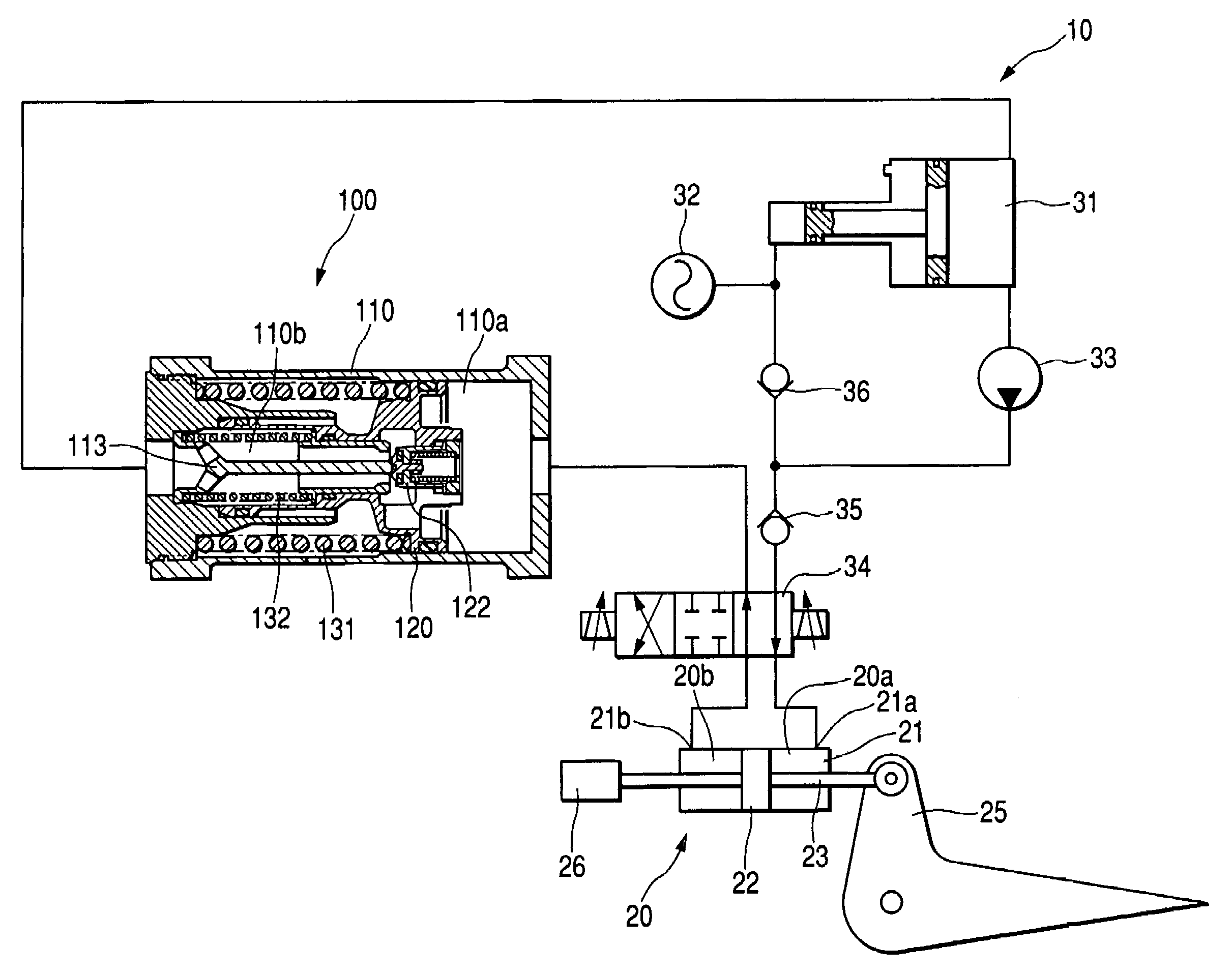
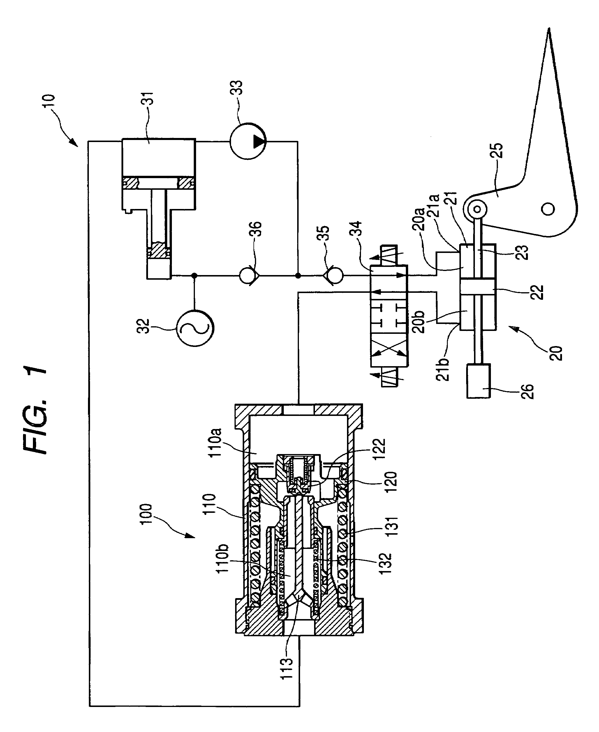
[0023]Firstly, the construction of an actuation system according to a first embodiment of the invention will be described.

[0024]As shown in FIG. 1, an actuation system 10 according to the embodiment of the invention includes a hydraulic cylinder 20 which is an actuator driven by virtue of oil. Here, the hydraulic cylinder 20 has a cylinder case 21, a piston 22 which is slidably accommodated within the cylinder case 21 and a piston rod 23 which is formed integrally with the piston 22. In addition, in the hydraulic cylinder 20, a cylinder chamber 20a and a cylinder chamber 20b are defined by the cylinder case 21 and the piston 22. Additionally, in the cylinder case 21, there are formed a supply / discharge port 21a which functions both as a supply port through which oil is supplied into the cylinder chamber 20a and a discharge port through which oil is discharged from the cylinder chamber 20a and a supply / discharge port 21b which functions both as a supply port through which oil is supp...

second embodiment

[0049]Firstly, the construction of an actuation system according to a second embodiment will be described. Note that according to the construction of the actuation system of this embodiment, the actuation system 10 (refer to FIG. 1) includes a back-pressure valve 200 shown in FIG. 4 in place of the back-pressure valve 100 (refer to FIG. 1).

[0050]The back-pressure valve 200 includes a case 210, a piston 220 accommodated slidably within the case 210 and a spring 231 which functions as an elastic member for urging the piston 220 in a sliding direction thereof.

[0051]Here, the case 210 has a first member 211 in which a hole 211a and a hole 211b are formed, a second member 212 which is fitted in the first member 211 and in which a hole 212a is formed, a projecting member 213 accommodated in the interior of the second member 212 and a stopper 214 for fixing the projecting member 213 to the second member 212. In addition, in the case 210, there are defined an oil chamber 210a as a first flu...

third embodiment

[0067]Firstly, the construction of an actuation system according to a third embodiment will be described. Note that according to the construction of the actuation system of this embodiment, the actuation system 10 (refer to FIG. 1) includes a back-pressure valve 300 shown in FIG. 5 in place of the back-pressure valve 100 (refer to FIG. 1).

[0068]The back-pressure valve 300 includes a case 310, a piston 320 accommodated slidably within the case 310 and a spring 331 and a spring 332 both of which function as an elastic member for urging the piston 320 in a sliding direction thereof.

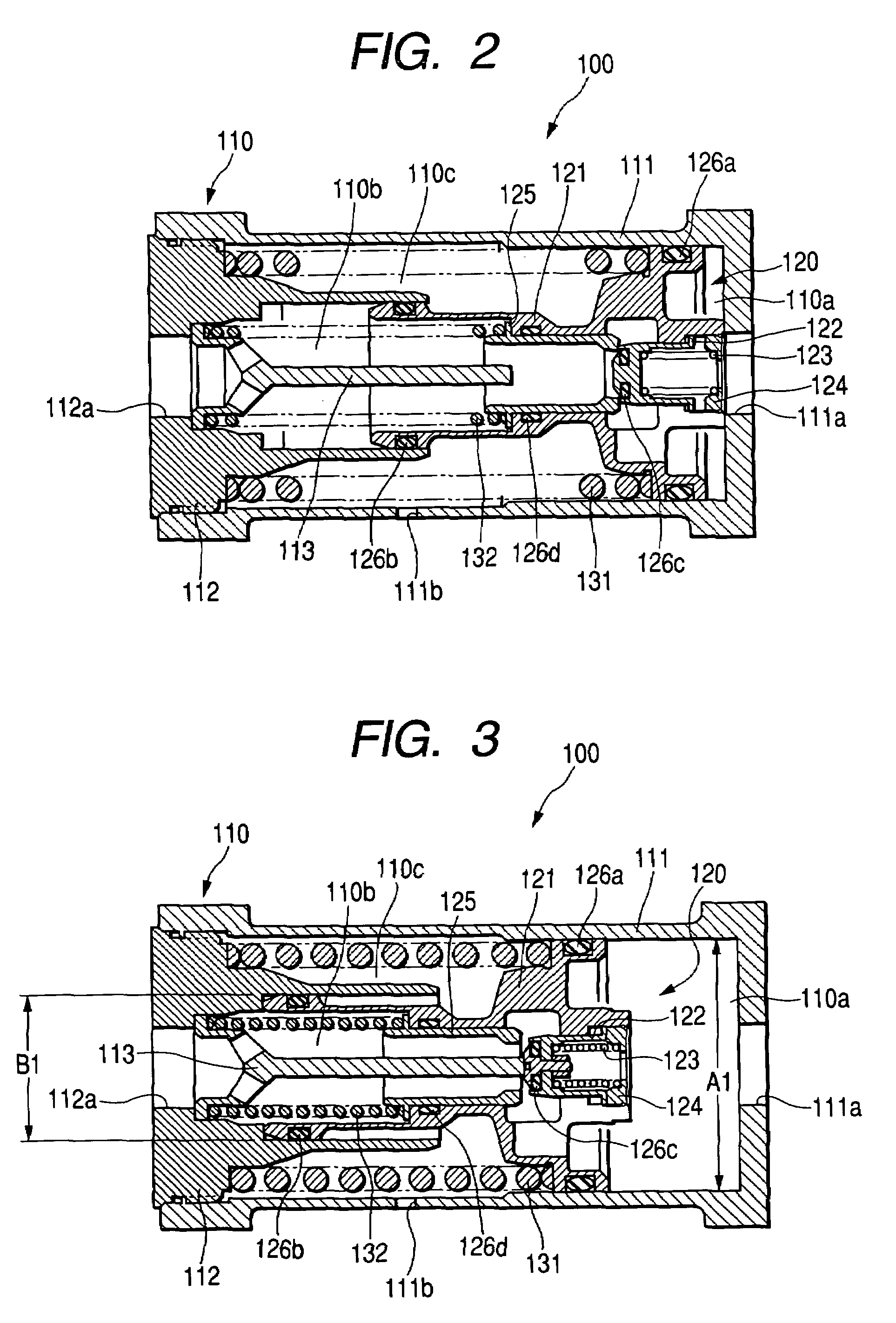
[0069]Here, as shown in FIG. 2, the back-pressure valve 100 includes a case 110, a piston 120 accommodated slidably within the case 110 and a spring 131 and a spring 132 both of which function as an elastic member for urging the piston 120 in a sliding direction thereof.

[0070]Here, the case 310 has a first member 311 in which a hole 311a and a hole 311b are formed and a second member 312 which is fitted in t...


PUM


Abstract

A back-pressure valve comprises a case having first and second oil chambers through which oil passes. A piston is slidably accommodated within the case to partition the first oil chamber and the second oil chamber. A spring urges the piston in a sliding direction. A projecting member and a check valve allow the first oil chamber to communicate with the second oil chamber when the pressure of the oil in the first fluid chamber reaches a predetermined pressure. An area of the piston on which oil pressure is received in the first oil chamber is made lager than an area on which oil pressure is received in the second oil chamber. A part of the piston located at an end thereof opposite to the end thereof which faces the first oil chamber communicates with the outside of the case.

Description

BACKGROUND OF THE INVENTION[0001]1. Field of the Invention[0002]The present invention relates to a back-pressure valve for applying a back pressure to an actuator or the like.[0003]2. Description of the Related Art[0004]There is known a pressure accumulator having a relief valve as a conventional back-pressure valve. See, for example, Japanese Patent Publication No. JP-A-9-328098 (Page 7, FIG. 1).[0005]In the conventional back-pressure valve, however, since there is generated a difference in hydraulic pressure between before and after the passage through the back-pressure valve, there has been caused a problem that hydraulic energy is lost.[0006]Furthermore, in the conventional back-pressure valve, since a predetermined pressure for a relief valve is set larger than a desired predetermined pressure therefor to some extent in order to ensure the accumulation of the desired predetermined pressure, there has been caused a problem that the loss of hydraulic energy is increased.SUMMARY O...

Claims


Application Information

Patent Timeline
Patent Type & Authority Patents(United States)
IPC IPC(8): F16D31/02F15B13/04B64C13/16F15B11/028F16K17/04F16K31/122
CPCF16K31/1226
Inventor KOIZUMI, TAKASHIKAMIMURA, TOSHIO
Owner NABLESCO CORP
Why Eureka
Try Eureka