Machine fluid supply assembly comprising keying means

a technology of machine fluid supply and keying means, which is applied in the direction of liquid dispensing, printing, ink receptacles, etc., can solve the problems of machine malfunction, increase in machine operating costs, and complex assembly

Inactive Publication Date: 2008-12-02
GEMPLU
View PDF21 Cites 83 Cited by
  • Summary
  • Abstract
  • Description
  • Claims
  • Application Information

AI Technical Summary

Benefits of technology

[0013]For the purpose of remedying those drawbacks, the invention provides an assembly for feeding fluid to equipment, in particular for feeding ink, which assembly includes a feed bottom base provided with a filling orifice communicating with at least one feed duct for feeding fluid to the equipment, the assembly being of the type in which the fluid is packaged in a top container provided with a feed opening which is organized to be connected to the filling opening of the feed base via a fitting that is pre-mounted on the container, and of the type including first axial locking means for mounting the fitting on the container and second axial locking means for mounting the fitting on the base, mounting the fitting on the base comprising moving the fitting in translation along a vertical mounting axis, then pivoting the fitting about the mounting axis, said assembly being characterized in that the fitting or the base is provided with at least one keying finger or at least one keying stud which, while the fitting is moving in translation, is received in groove segment or a channel segment that is matched and that is formed in one face of the base or of the fitting so that the container can be mounted only on a determined base as a function of the matching of the fitting with the base, said matching being defined by the keying finger or the keying stud co-operating with the matched groove segment or channels.

Problems solved by technology

Such a mounting error causes the machine to malfunction since the print patterns are then printed in the wrong colors.
Such a mounting error then requires the machine to be stopped to enable the feed circuits for feeding ink to the machine to be cleaned, thereby rendering the machine unavailable for a long period, and causing an increase in machine operating costs.
That assembly is complex and it does not solve the problem of matching each ink bottle of a determined color with a determined base.

Method used


Image

  • Machine fluid supply assembly comprising keying means
  • Machine fluid supply assembly comprising keying means
  • Machine fluid supply assembly comprising keying means

Examples


first embodiment

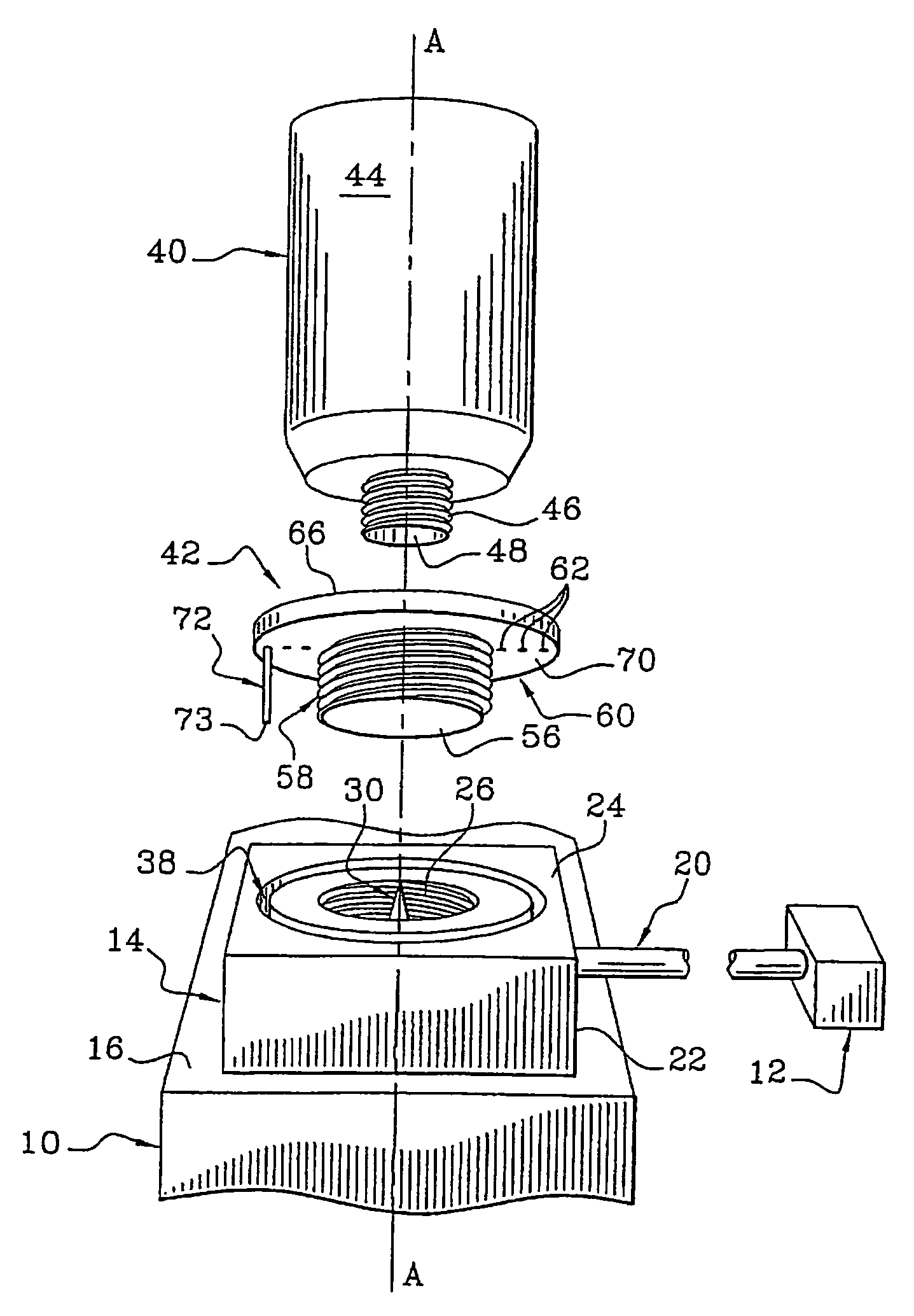
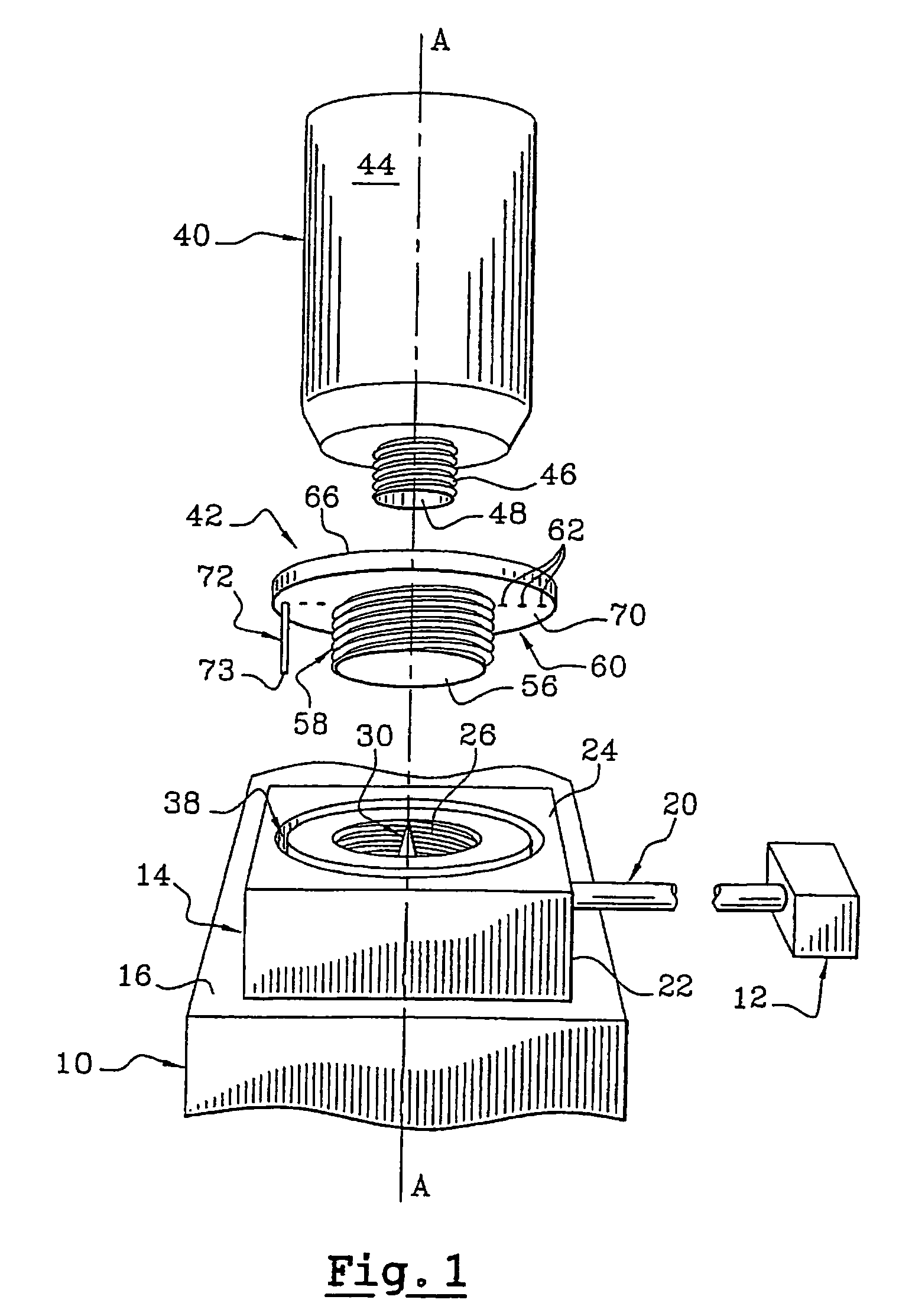
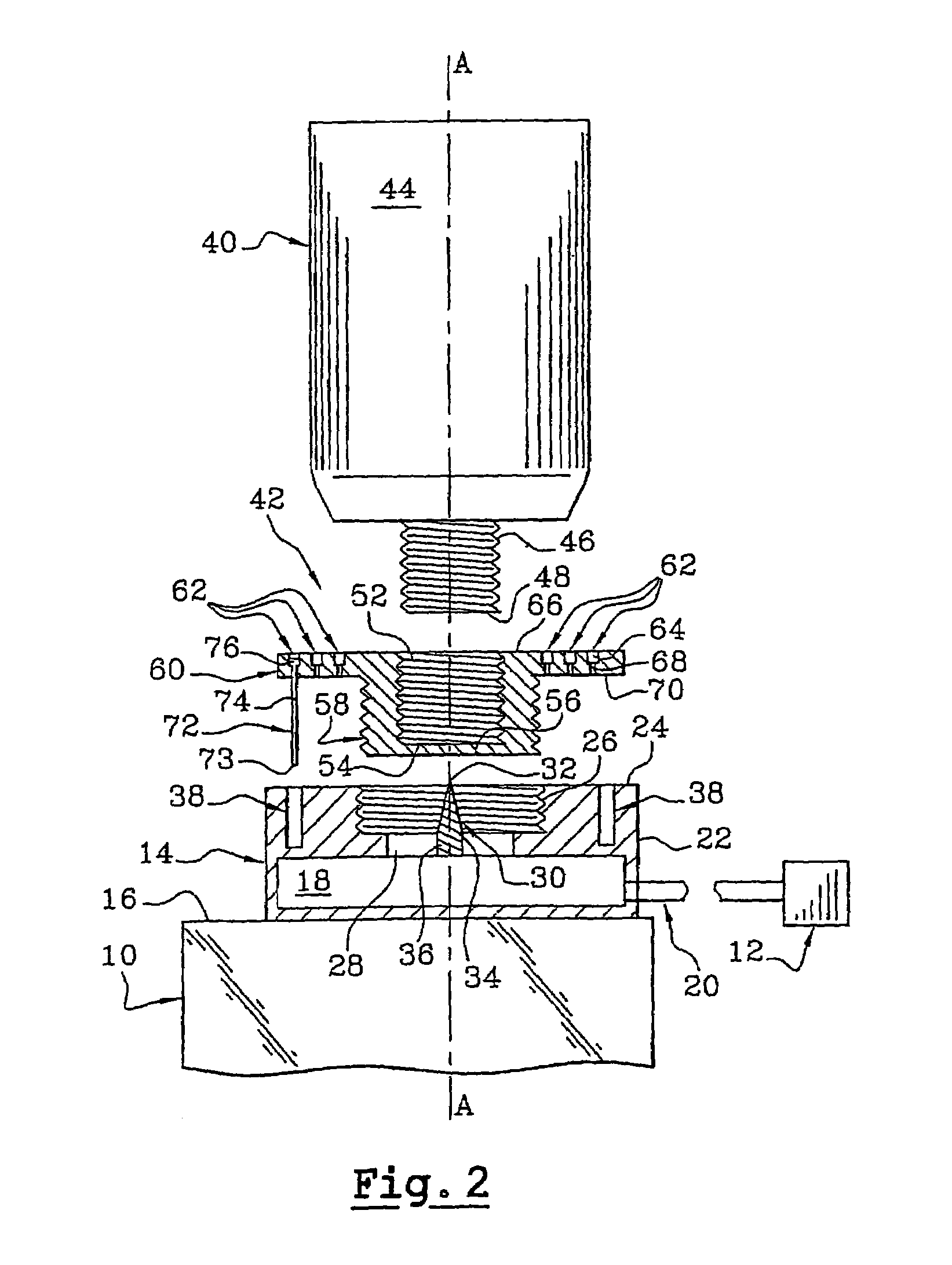
[0047]FIGS. 1 to 6 show an assembly of the invention for feeding fluid to an industrial printing machine 10.

[0048]The printing machine 10 has a plurality of print heads 12, only one of which is shown in FIGS. 1 and 2, and which are controlled, for example by an electronic control unit (not shown), and it includes an ink feed base 14 or a pump base which is associated with each print head 12.

[0049]In the description below, in order to make the invention easier to understand, a vertical configuration is used by way of non-limiting example, corresponding to a top-to-bottom configuration in FIGS. 1, 2, 5, and 6.

[0050]The feed base 14, which is substantially rectangular block shaped in this example, is mounted on a top wall 16 of the machine 10, and it has a feed chamber 18 in a bottom half that communicates with the associated print head 12 via a feed duct 20.

[0051]The feed duct 20 is connected upstream to the feed chamber 18 via one of its side walls 22.

[0052]The top face 24 of the fee...

second embodiment

[0107]FIGS. 7 to 11 show an assembly of the invention.

[0108]The assembly differs from the first embodiment mainly by its fitting 42 and by its base 14 that carry different keying and locking means.

[0109]As can be seen in the exploded view of FIG. 7, the base 14 is provided with a separate element in the form of a tubular sleeve 78 which, in this example, is coaxial with the mounting axis A-A.

[0110]In a variant embodiment, the sleeve 78 could be formed integrally with the top face 24 of the base 14.

[0111]The concave axial wall 80 of the sleeve 78 defines the filling hole 26 of the base 14.

[0112]FIG. 8, in which the sleeve 78 is shown in perspective, shows that the sleeve 78 has a convex axial wall 82 and a top axial end transverse surface 84 and a bottom axial end transverse surface 86.

[0113]In this example, the sleeve 78 is provided with two axial holes 88, 90 that are diametrically opposite and that open out in both of the axial end transverse surfaces 84 and 86.

[0114]The sleeve 78...


PUM


Abstract

The invention relates to a fluid supply assembly for a device, particularly a printing machine. The assembly includes a lower base and is of the type in which the fluid is conditioned in an upper container which is intended to be connected to a fill opening in the base by a coupling. In order to mount the coupling on the base, the coupling is moved linearly along a vertical assembly axis and then pivoted around the assembly axis. The coupling has at least one keying pin which is received in a complementary groove in one face of the base when the coupling is being moved linearly. The invention also relates to a printing machine containing one such assembly.

Description

BACKGROUND OF THE INVENTION[0001]The invention relates to an assembly for feeding fluid to equipment.[0002]The invention relates more particularly to an assembly for feeding fluid to equipment, in particular for feeding ink, which assembly includes a feed bottom base provided with a filling orifice communicating with at least one feed duct for feeding fluid to the equipment, the assembly being of the type in which the fluid is packaged in a top container provided with a feed opening which is organized to be connected to the filling opening of the feed base via a fitting that is pre-mounted on the container, and of the type including first axial locking means for mounting the fitting on the container and second axial locking means for mounting the fitting on the base, mounting the fitting on the base comprising moving the fitting in translation along a vertical mounting axis, then pivoting the fitting about the mounting axis.[0003]The invention is described herein with reference to p...

Claims


Application Information

Patent Timeline
Patent Type & Authority Patents(United States)
IPC IPC(8): B41J2/175B67D5/00B64C27/28B41F31/02B65D83/00B67D99/00
CPCB41J2/17509B41J2/17523B41J2/1755
Inventor BATISTA, JEAN-MARCSARRA-BOURNET, PHILIPPE
Owner GEMPLU
Why Eureka
Try Eureka