Multi purpose radar surveillance system

a radar surveillance and multi-purpose technology, applied in the field of radar systems, can solve the problems of system complexity, high cost, and current methods for detecting forest fires, and achieve the effects of low maintenance, low observability targets, and low cost of deploymen

Active Publication Date: 2008-12-02
TELEFON AB LM ERICSSON (PUBL)
View PDF7 Cites 2 Cited by
  • Summary
  • Abstract
  • Description
  • Claims
  • Application Information

AI Technical Summary

Benefits of technology

[0008]By means of the system of the invention, detection of low observability targets becomes possible by means of a plurality of individual stations which are simple and thus inexpensive, which require low maintenance and are inexpensive to deploy.

Problems solved by technology

Current methods for detecting forest fires are relatively expensive and complicated.
A “manual” method of detecting forest fires is by means of overflights of small aircraft, which is expensive.
Some drawbacks which this system seems to suffer from are that the system is relatively complicated in that it involves moving parts and sensors of different kinds.

Method used


Image

  • Multi purpose radar surveillance system
  • Multi purpose radar surveillance system
  • Multi purpose radar surveillance system

Examples


Embodiment Construction

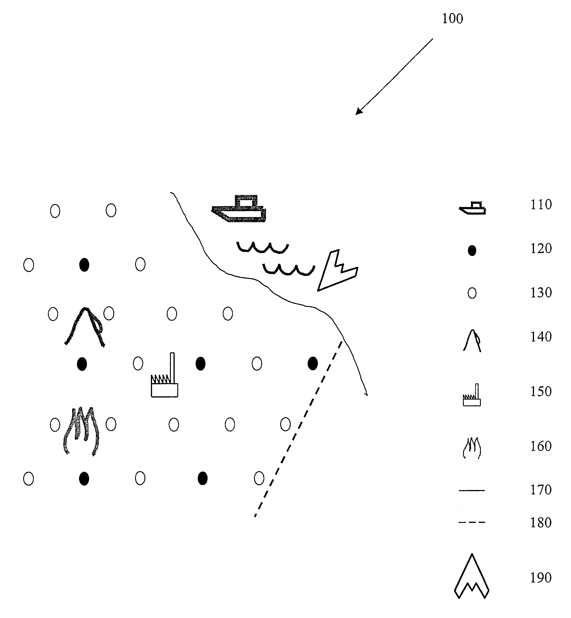
[0013]In FIG. 1, a system 100 of the present invention is schematically shown. The drawing comprises objects to be detected by the system, such as a surface craft 110, an avalanche 140, a sensitive object 150, such as, for example, a power plant, a forest fire 160, and an aircraft 170, in this example an aircraft with low Radar Cross Section (RCS). Since the system of the invention has the ability to detect objects with low RCS, the system also inherently has the ability to detect objects with larger RCS.

[0014]Also shown in the drawing are examples of system components, with reference numbers as follows: transmit stations 120 and receive stations 130, said stations being intended for transmitting and receiving, respectively, electromagnetic energy.

[0015]The continuous line shown in FIG. 1 depicts a coastal line, and the dotted line in FIG. 1 shows a border between two areas, countries etc.

[0016]Thus, FIG. 1 shows an example of low RCS-objects which it might be desired to detect, suc...


PUM


Abstract

The invention discloses a radar system (100) for the detection of low RCS-objects (110, 140, 150, 160, 190) such as forest fires, said system comprising a first plurality of stations (120) for transmitting radar energy, said stations having mechanically fixed antennas (220), and a second plurality of receive stations (130) for receiving reflections of radar energy transmitted from the transmit stations, said stations having mechanically fixed antennas (220). The antennas (220) of said transmit and receive stations have a main beam (221) which is essentially parallel to the ground, and at least a sub-set of the receive stations is equipped with means for recording a first and a second received signal, and means for subtracting one of said signals from the other of said signals. Said transmit and receive stations are arranged to function within the frequency range of 10-100 MHz.

Description

TECHNICAL FIELD[0001]The present invention discloses a radar system for the detection of low Radar Cross Section-objects such as forest fires, the system comprising a first plurality of transmit stations for transmitting radar energy which have mechanically fixed antennas. The system also comprises a second plurality of receive stations for receiving reflections of radar energy transmitted from the transmit stations, said stations having mechanically fixed antennas. In the system of the invention, the antennas of said transmit and receive stations have a main beam which is essentially parallel to the ground.BACKGROUND ART[0002]Current methods for detecting forest fires are relatively expensive and complicated. A “manual” method of detecting forest fires is by means of overflights of small aircraft, which is expensive. A known automated system for detecting forest fires is disclosed in U.S. Pat. No. 5,959,589. Some drawbacks which this system seems to suffer from are that the system ...

Claims


Application Information

Patent Timeline
Patent Type & Authority Patents(United States)
IPC IPC(8): G01S13/00
CPCG01S7/412G01S13/003G01S13/04G01S7/003
Inventor RIVAS, CONRADORIVAS, PATRIKHOOK, ANDERS
Owner TELEFON AB LM ERICSSON (PUBL)
Why Eureka
Try Eureka