Method and apparatus for detecting sources of projectiles

a projectile source and source technology, applied in the field of efield sensors, can solve the problems of difficult to determine the position of the closest approach to an acoustic sensor, it is virtually impossible to detect which individual sound trails belong to which shooters, and the acoustic means are not particularly useful in identifying the shooter or his location

Inactive Publication Date: 2010-07-27
BAE SYST INFORMATION & ELECTRONICS SYST INTERGRATION INC
View PDF4 Cites 31 Cited by
  • Summary
  • Abstract
  • Description
  • Claims
  • Application Information

AI Technical Summary

Benefits of technology

[0018]Moreover, the size of the array can be minimized due to the use of the E-field sensors. If the sensor array has elements at the corners of a square, the array need only be 16 inches on a side. Moreover, the E-field sensor detector, filtering, and processing can be accomplished in a compact module that is exceptionally lightweight, with the E-field sensor in essence being only a conductive pad on a substrate. Thus its extent is minimized to contribute to low observability.
[0020]Moreover, if needs a device to be used in a crowd of people, knowing the shooter's direction, one can shine a high intensity strobe light or high intensity dazzler at the shooter and only need an aiming accuracy of 10 to 15 degrees. The result is that the shooter is dazed due to the non-lethal countermeasure. Thus line fire in a crowd can be avoided.
[0022]Moreover, with respect to UAVs, again it is a simple matter to mount an E-field array and attendant circuitry on the UAV. Because of the low power consumption of the E-field devices themselves and because of the particular filtering system to be described, which limits the amount of processing power necessary to eliminate clutter and the effects of power line E-field disturbances, it has been calculated that one could, on a simple four double-A battery configuration, operate for 24 hours. Power consumption for processing the incoming information and slewing a laser to illuminate the direction of the incoming round is reduced to a minimum to achieve the 24-hour limit. Thus, for instance, with an AK-47 firing about 10 rounds a second, one has about 100 milliseconds to do processing before the next round is on its way. Using a very low power processor, and noting that a human being cannot respond in a tenth of a second anyway, one can detect a bullet every minute. For 24 hours, this means that the system can detect and track 1,440 rounds on one battery charge.
[0024]While it is possible to use differential E-field sensors in which the sensor itself comprises two E-field antennas, the outputs of which are differentially amplified, the single-ended sensor is preferred, with the dE / dT zero crossing providing an accurate time indication of the closest approach of a projectile. Moreover, the problems associated with acoustic sensors are completely eliminated by using the E-field sensor array, which is effective not only for subsonic rounds but also in the multiple shot environments. Thus individual shooters can be isolated from the multi-shot clutter due to the relatively short range at which the particular E-field sensors operate.

Problems solved by technology

However, there are a number of problems involved in ascertaining the source of the projectile acoustically, mainly centering around the arrival of reverberations.
Additionally, in a firefight or when there are multiple rounds being fired, it is virtually impossible to detect which individual sound trails belong to which shooters.
The result is that acoustic means are not particularly useful in identifying the shooter or his location.
There is also another problem associated with acoustic determination of the position of a projectile and that is the fact that the shock wave extends out from the forward portion of the projectile some distance behind it.
Thus, the position of closest approach to an acoustic sensor is not easily ascertained.
As a result, it is not easy to determine what part of the shock wave has been sensed in order to ascertain source location.
This inability to specify closest approach impacts the time delay measurement between the sensors that is used to triangulate on the position of the projectile.
A further problem with acoustic sensing is that the speed of sound plays a factor so that pinpointing a projectile and determining its trajectory is either delayed or requires a relatively large baseline for the acoustic array sensors.
This baseline in and of itself is problematic due to the large array configuration.
It is unwieldy and very visible.
Additionally, the large arrays such as acoustic arrays are not easily man-portable.
When an individual attempts to erect an acoustic array, for instance in a foxhole, not only do the confines of the foxhole make deployment awkward, the presence of the individual is readily ascertainable due to the bulky array that is projected above the foxhole.
The problem with the acoustic sensors, as mentioned above, is that the enemy quickly learns which ones to shoot at and which ones not to.

Method used


Image

  • Method and apparatus for detecting sources of projectiles
  • Method and apparatus for detecting sources of projectiles
  • Method and apparatus for detecting sources of projectiles

Examples


Embodiment Construction

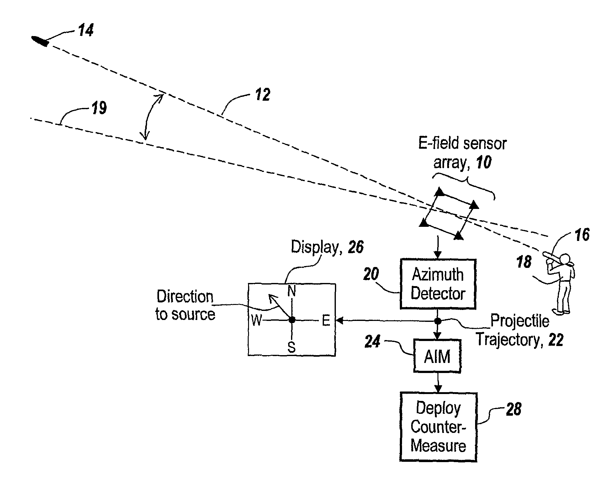
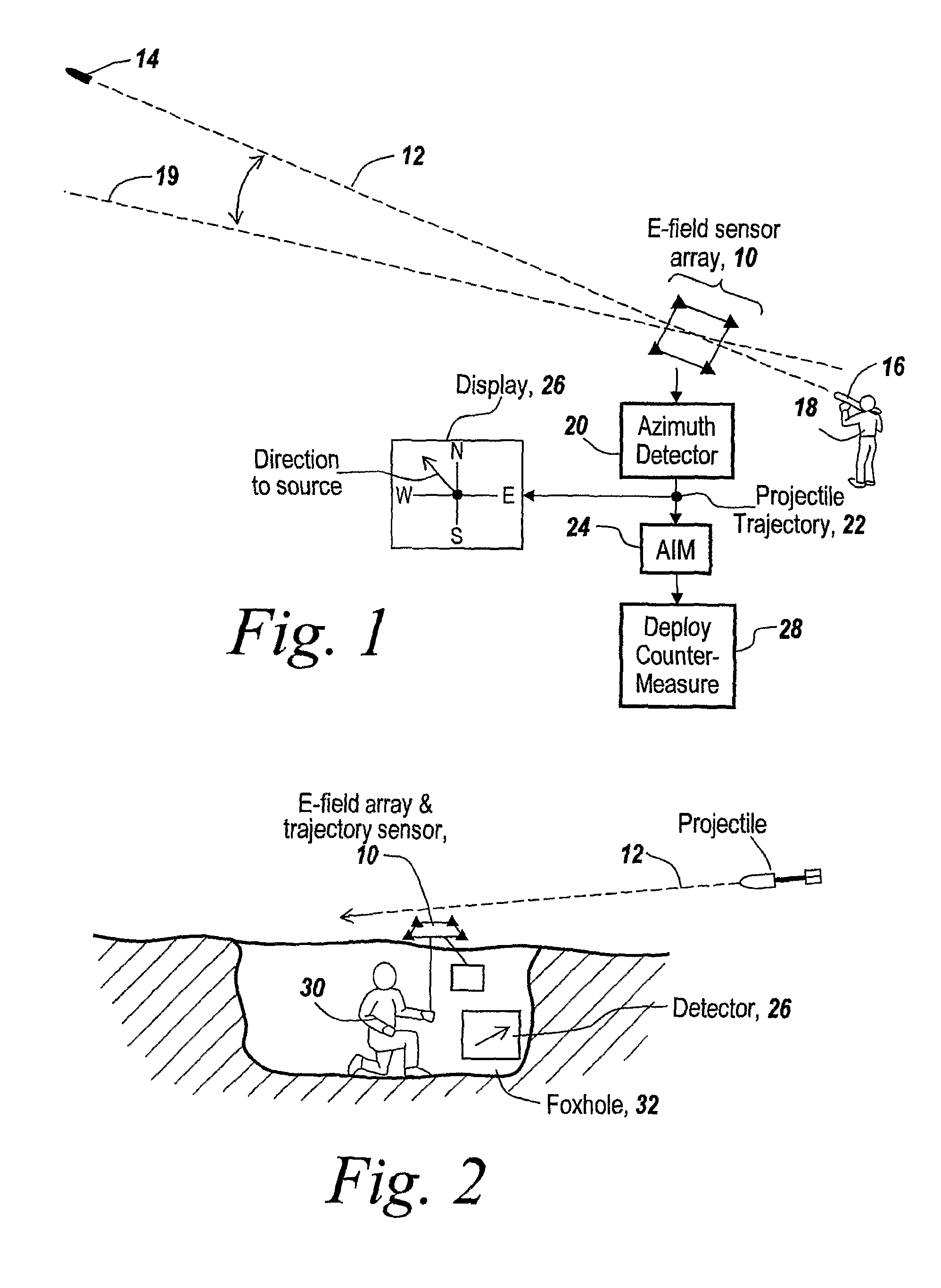
[0043]As shown in FIG. 1, in the subject invention, an E-field sensor array 10 is used to detect the trajectory 12 of a projectile 14 as it passes near an E-field sensor, which projectile may be a bullet from a rifle 16 fired by an individual 18, with the trajectory measured from the E-field center line 19.

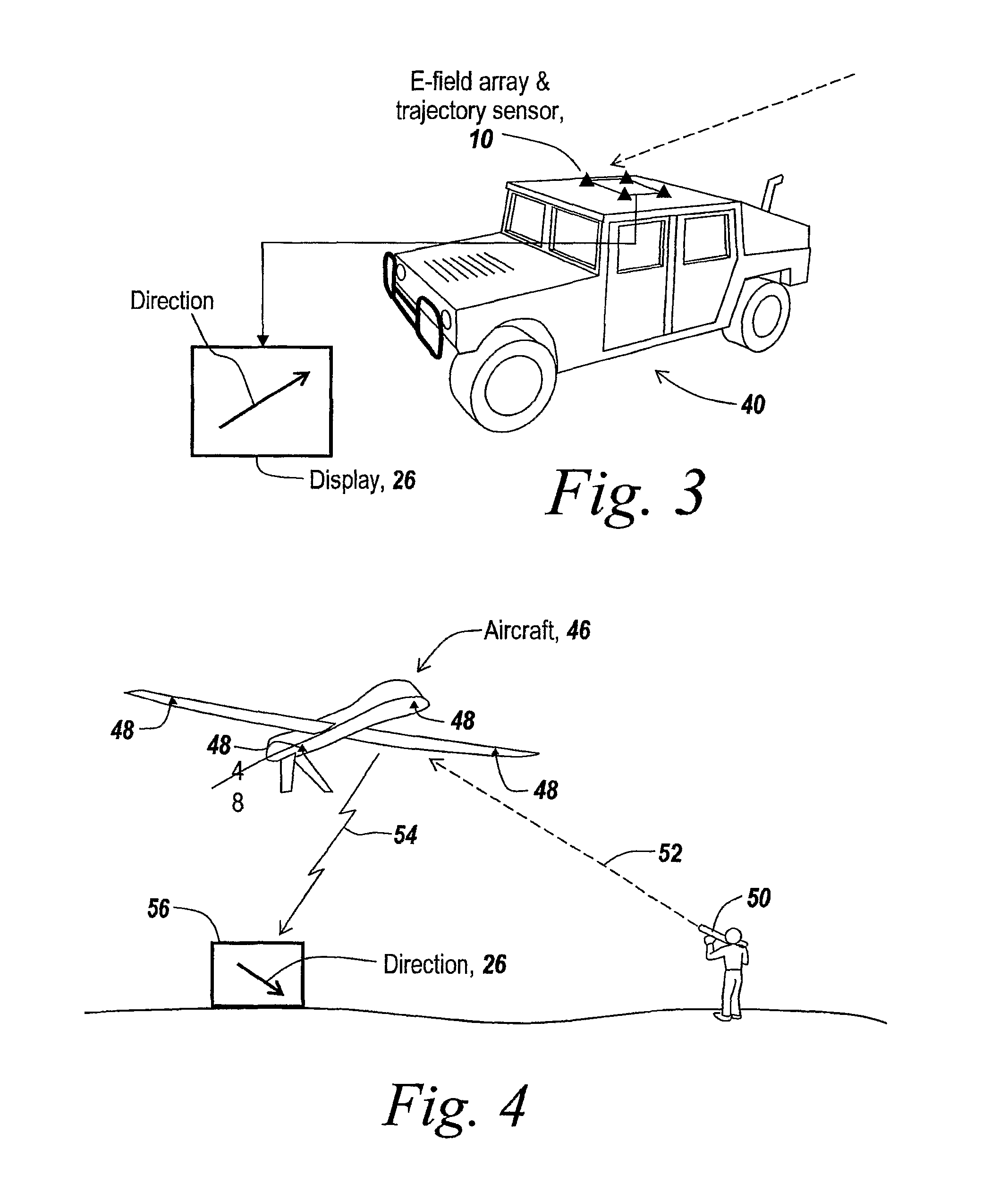
[0044]The disturbance in the local electric field caused by the passage of a charged projectile is detected by the E-field sensor array. The output of the array is coupled to a processing unit 20 that processes the output of the E-field sensors and outputs the projectile trajectory bearing 22. The bearing is either used to aim an ordnance illustrated at 24 or to display the direction to the source of the projectile as illustrated by display 26.

[0045]The aiming unit may be used to deploy any type of countermeasure, for instance such as the projection of a laser beam back to the source of the projectile. Additionally, the aiming unit may be used to aim a dazzler to disorient the ind...


PUM


Abstract

What is provided is the use of an array of E-field sensors to detect the closest approach of incoming projectiles and to determine through time difference of arrival the bearing of the incoming projectile, thus to identify the bearing of the source of the projectile. dE / dT processing of the individual outputs of the E-field sensors indicates by the zero crossing the peak of the E-field disturbance and thus the instance of time of the closest approach of the projectiles to a sensor.

Description

RELATED APPLICATIONS[0001]This Application claims rights under 35 USC §119(e) from U.S. Application Ser. No. 60 / 578,745 filed Jun. 10, 2004, entitled “Method and Apparatus for Detecting Sources of Projectiles,” and is a continuation in part of U.S. patent application Ser. No. 10 / 917,793, filed Aug. 12, 2004, which is a continuation in part of PCT / US03 / 04092 filed Feb. 12, 2003, entitled “Method to Detect and Determine Bearing to a Rocket Launch or Muzzle Blast,” the contents of which are incorporated herein by reference.FIELD OF THE INVENTION[0002]This invention relates to E-field sensors and more particularly to the use of E-field sensors in determining the trajectory of a projectile.BACKGROUND OF THE INVENTION[0003]It will be appreciated that a number of attempts have been made to determine the trajectory of an incoming round or bullet in order to be able to isolate the shooter and to provide what other measures are necessary in order to neutralize the threat. To do so, it has bee...

Claims


Application Information

Patent Timeline
Patent Type & Authority Patents(United States)
IPC IPC(8): G01C17/00
CPCG01S5/00G01S5/06G01V3/088
Inventor ZANK, PAUL A.MERCIER, MICHAEL
Owner BAE SYST INFORMATION & ELECTRONICS SYST INTERGRATION INC
Why Eureka
Try Eureka