Recliner mechanism

a technology of reclining mechanism and seat, which is applied in the direction of movable seats, vehicle components, vehicle arrangements, etc., can solve the problems of less durable components, higher manufacturing and assembly costs, and large size, and achieve the effect of improving and robust high strength design

Inactive Publication Date: 2008-12-09
JOHNSON CONTROLS TECH CO
View PDF55 Cites 9 Cited by
  • Summary
  • Abstract
  • Description
  • Claims
  • Application Information

AI Technical Summary

Benefits of technology

[0008]It is an object of the present invention to provide an improved, robust high strength design for a seat recliner mechanism.
[0009]It is another object of the present invention to provide an improved vehicle recliner mechanism having a compact design.
[0011]It is still another object of the present invention to provide an improved automobile seat recliner that is less complex in design than known conventional seat recliners.
[0012]It is another object of the present invention to provide an improved automobile seat recliner that can achieve all of the above objects in a single recliner mechanism.
[0013]One embodiment of the present invention relates to a recliner mechanism and seat assembly that results in a robust system that fits in a compact space while having a lower cost to manufacture and assemble. The recliner mechanism of the present invention includes fewer moving parts thereby reducing the system's overall complexity.
[0017]According to one embodiment, one of the cam pins has a lever member to be used has a handle by a user to operate the recliner mechanism. The lever member is biased into a first or locked position in which first and second pawl members engage the sector member and the seat back can not be rotated with respect to the seat base. A coil spring is used to bias the lever member such that the recliner mechanism in the locked position. A user may exert a sufficient force on the lever member to overcome the force of the coil spring and cause the cam pins to rotate, thereby causing the first and second pawl members to rotate out of engagement from the sector member to an unlocked or operating position. Thus, rotation of the lever member results in a rotation of the pawl members about the common pivot connection at the opposite ends of the pawl members, causing the pawl members to move away and disengage from the notched edge of the round sector member in a “scissors-type” action. When the recliner mechanism is in the unlocked position—the notched edges of the pawl members are disengaged from the notched edge of the round sector member—the seat back may rotate relative to the seat base.

Problems solved by technology

Other mechanisms use highly complex arrangements of components resulting in greater size, complexity and cost.
An increased number of parts or the use of high-strength materials, however, also often result in a higher cost to manufacture and assemble.
If lower cost, less durable components are used, however, the overall strength of the recliner mechanism will be negatively affected, resulting in lower customer satisfaction and quality.
However, while the above prior art patents disclose numerous mechanisms for moving the pawl members into and out of engagement with the sector member, none do so in a highly simple and efficient manner while providing a sufficiently strong recliner mechanism that will perform adequately in the varied conditions of an automotive seat.
However, with the increased number of pawl members, the complexity associated with operating the pawl members and maintaining proper operating conditions of the recliner mechanism increases as well as the total weight of the recliner mechanism.
Further, while it is known to move the pawl members with respect to the round sector gear using various known mechanisms such as cams to translate, rotate or otherwise move the pawl member with respect to the round sector gear, such mechanisms have proven inadequate since there remains an insufficient amount of contact between the pawl member and the round sector gear to carry and distribute the substantial loads in the recliner mechanism.

Method used


Image

  • Recliner mechanism
  • Recliner mechanism
  • Recliner mechanism

Examples


Embodiment Construction

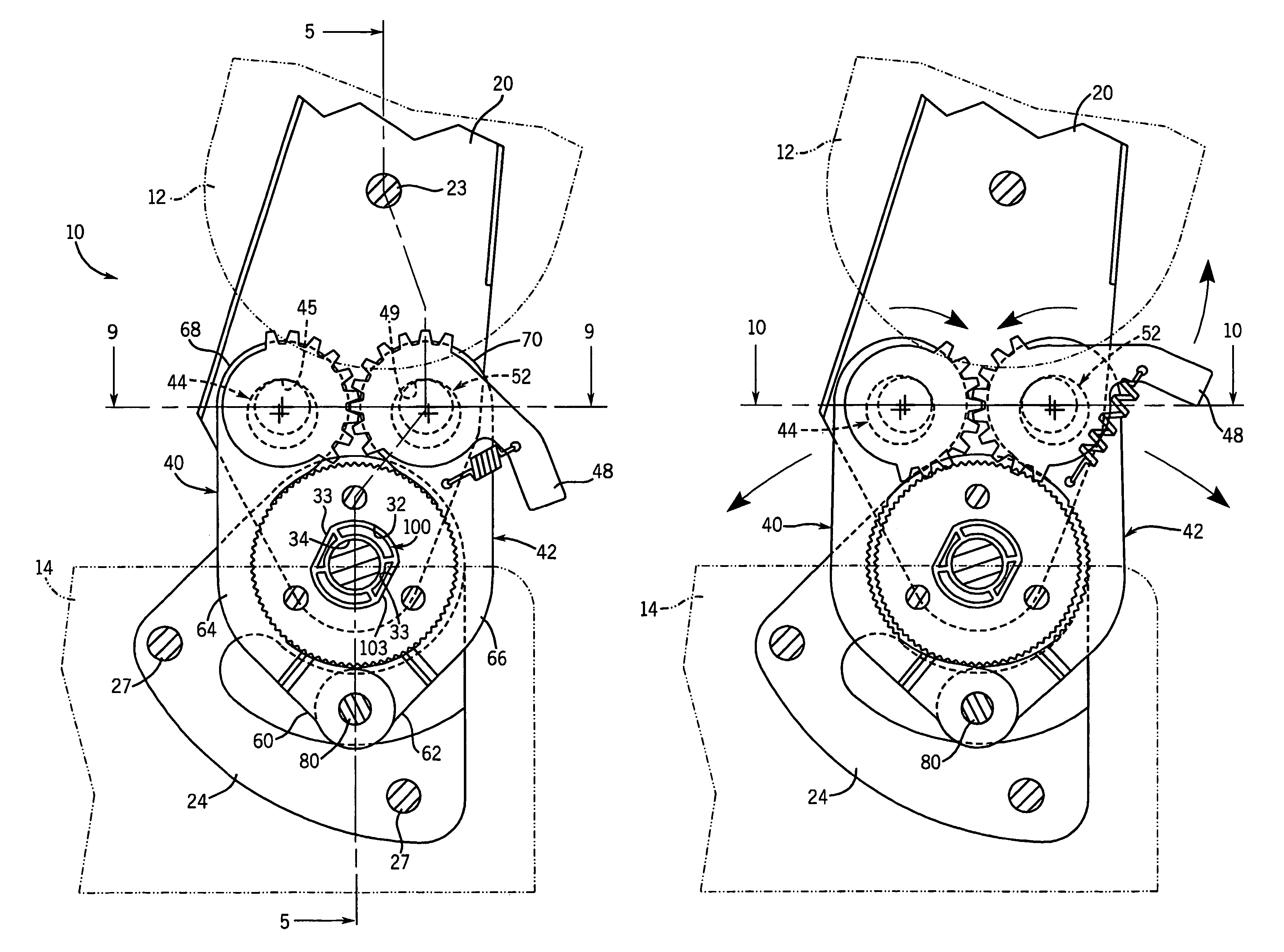
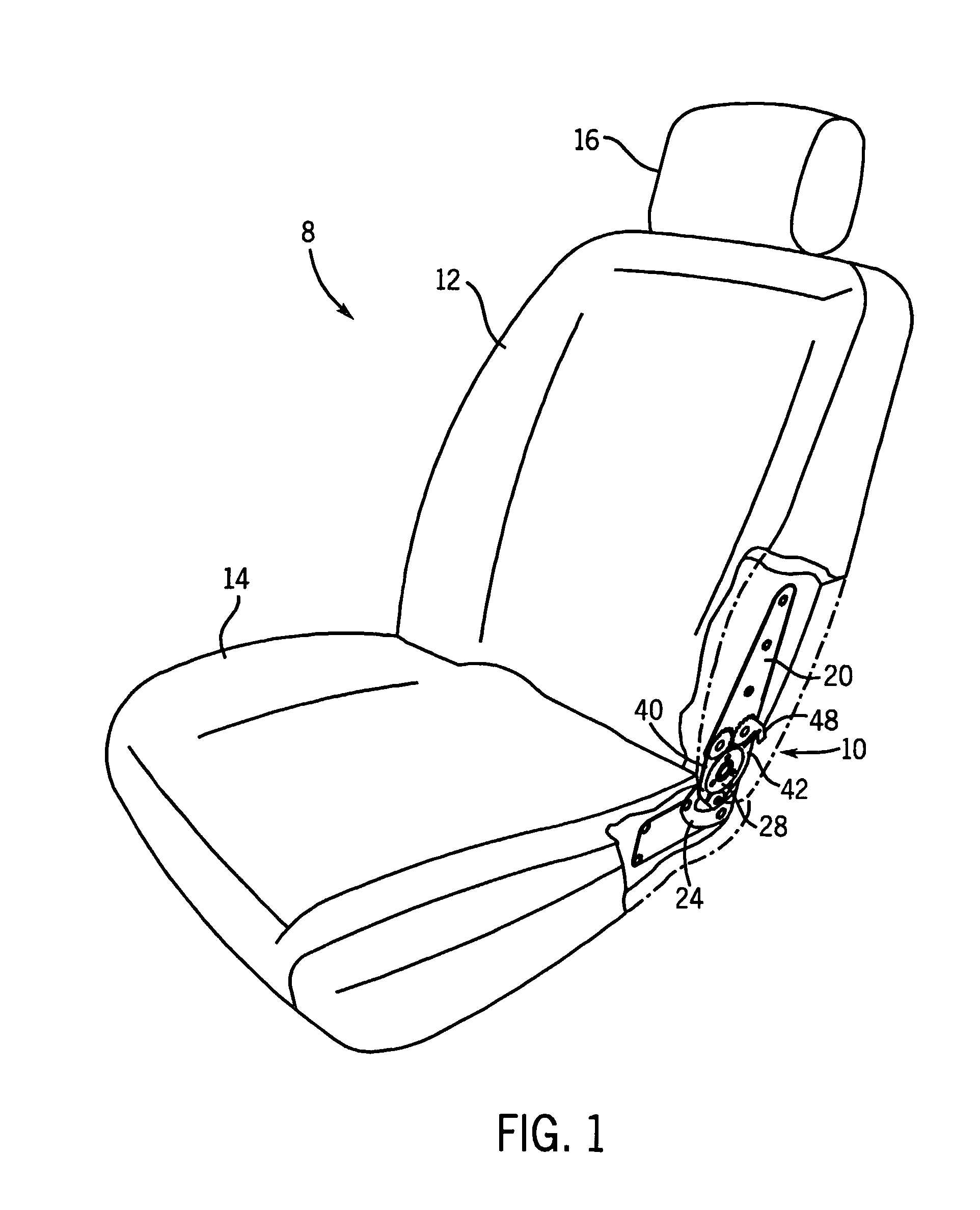
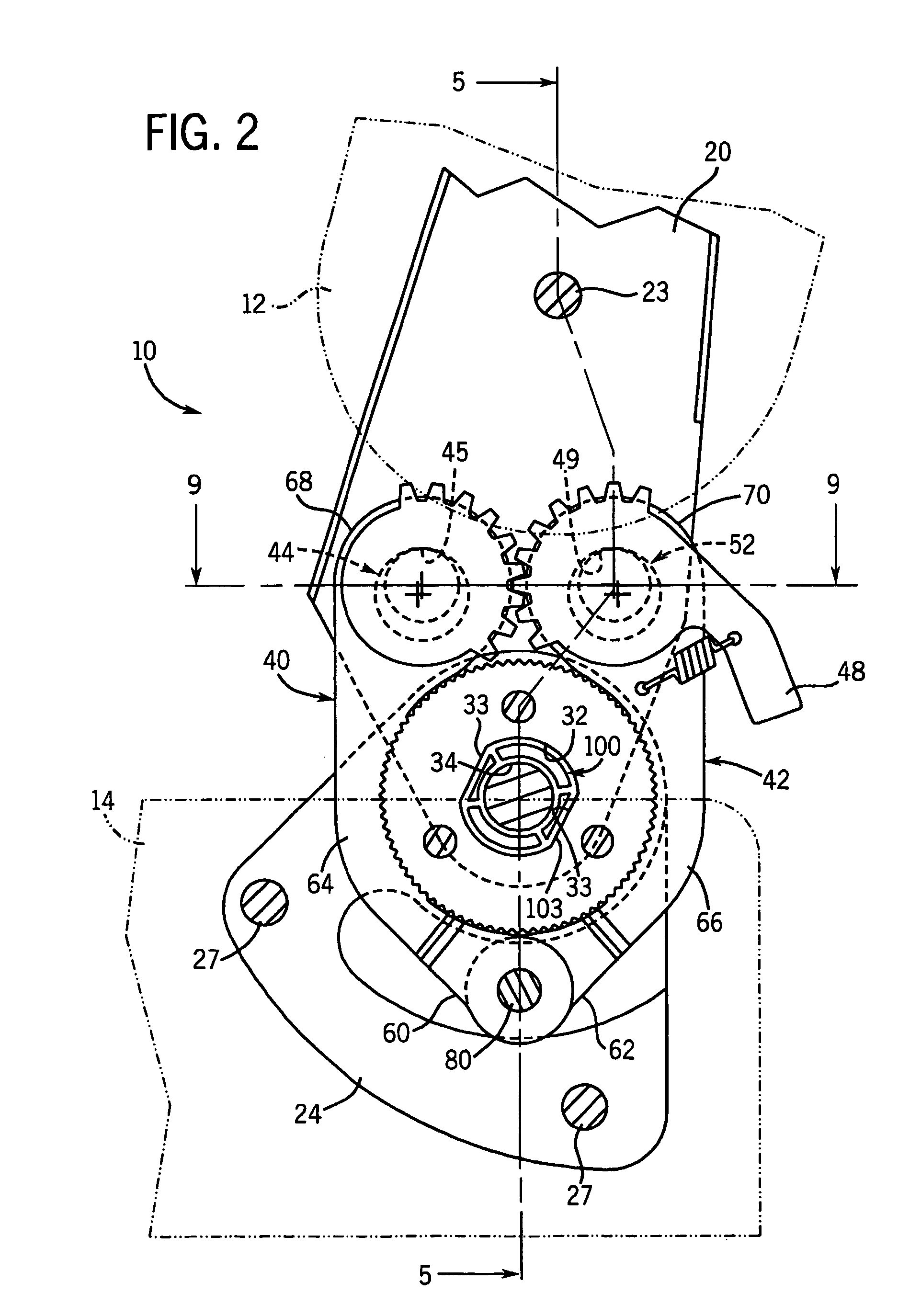
[0030]Referring generally to FIGS. 1-6 and in particular to FIGS. 1-4, there is shown a vehicle seat 8 having a section cut away in FIG. 1 to show a recliner mechanism 10. The seat 8 includes a seat back 12 and a seat base 14 of any appropriate or conventional design and general construction. The seat back 12 includes a first seat back frame or member 20 and a second seat back frame or member 22 (see FIG. 5). The first and second seat back members 20 and 22, respectively, are formed to create a space 21 there between to receive at least a portion of the recliner mechanism 10. The first and second seat back members 20 and 22, respectively, are connected using any known or appropriate coupling device such as a bolt 23. The first and second seat back members 20 and 22, respectively, are made from any known or appropriate material as is known in the industry of designing recliner mechanisms and preferably from a metal such as steel or a steel alloy. The seat back has other standard or k...


PUM


Abstract

A recliner mechanism for a vehicle seat includes a toothed sector member secured to a seat frame and first and second pivoted pawl members each including a plurality of teeth to engage the teeth of the sector member. The first and second pawl members also each pivot on a cam pin member located at a distal end thereof, the cam pins each have a center axis and an offset axis having by a toothed cam lobe. The toothed cam lobes mesh such that rotation of one cam pin member causes the other cam pin member to totate in the opposite direction. A handle is coupled to at least one of the cam pin members to rotate the cam pin members and cause the pawl members to rotate about a pin connecting the proximal ends of the pawl members. The pawl members are movable between a first or locked position and a second or unlocked position, permitting the seat back to be adjusted with respect to the seat base against the force of a spring.

Description

FIELD OF THE INVENTION[0001]The present invention relates generally to recliner mechanisms. More particularly, the present invention relates to a low cost, thin profile, pawl and sector recliner mechanism for use in adjusting the position of a seat back with respect to a seat base.BACKGROUND OF THE INVENTION[0002]Vehicle and other seats commonly include a recliner mechanism to adjust the position of the seat back relative to the seat base. Such manual recliner mechanisms often include a lever handle located on a side of the vehicle seat for actuation of the recline feature by the occupant. When the occupant desires to change the position of the seat back, he or she actuates the lever, unlocking the seat back typically against the force of a spring biasing the seat back in a given direction, most commonly in the forward direction. With the recliner mechanism released, the occupant is free to alter the position of the seat back relative to the seat base. The position of the seat back ...

Claims


Application Information

Patent Timeline
Patent Type & Authority Patents(United States)
IPC IPC(8): B60N2/235B60N2/22
CPCB60N2/2352
Inventor SEIBOLD, KURT A.
Owner JOHNSON CONTROLS TECH CO
Why Eureka
Try Eureka