
Method and device for processing a multi-channel measurement of magnetic fields

a multi-channel measurement and signal technology, applied in the field of multi-channel measurement signal processing, can solve the problems of erroneous results, affecting the accuracy of the signal, so as to achieve the effect of improving accuracy, reducing computational complexity, and improving accuracy

Active Publication Date: 2008-12-09
MEGIN OY
View PDF8 Cites 11 Cited by
  • Summary
  • Abstract
  • Description
  • Claims
  • Application Information

AI Technical Summary

Benefits of technology

[0024]Further, the method in accordance with the invention enables one to correct the signal distortions that are due to the movement of an object to be examined faster and more accurately than by previous methods, which is a basic requirement of a real-time correction for movement. The correction for movement is performed by representing the movement of an object to be examined as a movement of, the measurement sensors in the vicinity of a stationary object in such a manner that the variable geometry is taken into account when calculating the basis for signal space. In that case, the series development components corresponding to the object to be examined always are commensurable irrespective of the position of the object. The advantage of the invention is based on the fact that the calculation of the series development components requires quite few computational operations and on the fact that the external interferences are modelled when calculating the values of the series development components. Thus, this enables one to quickly calculate dependable values for the series development components corresponding to an interesting source area, although the distance and position of the object with respect to the measurement sensors would considerably vary and although the field structure of the external interferences would vary during the measurement.
[0025]Further, as the series development components describe the field produced by the sources everywhere in the measurement volume V1, they can be used to calculate a signal which would be measured by any fictitious sensor disposed in the same space. Virtual signals of this kind are useful e.g. when there is a wish to represent the signal produced by an object to be examined always in the same geometry irrespective of the fact of where the object was really situated during the measurement in relation to the measurement sensors. In addition, in virtual signals, the proportion of measurement errors is smaller than in original signals, as in the method one has attenuated the portion that is not included in the set model of an irrotational, sourceless vector field. Even in the case of virtual signals, the invention has the advantage of separating external interferences from the signals of an object to be examined.
[0026]In addition, the method in accordance with the invention enables one to identify individual sensors the signal measured by which clearly differs from the series development model that is based on the signals of the whole set of sensors. Thus, the method enables even a real-time quality control of measurement channels and an automatic rejection based on the signal analysis. In addition, the co-ordinates of the signals with respect to a basis in accordance with the invention can be re-calculated after the rejection of channels that operate in a non-desired manner, which enables one to obtain a more accurate result for the co-ordinates.
[0027]Further, thanks to the invention, the calibration of a measuring device or of a measurement geometry becomes easier than before. The calibration method in accordance with the invention does not need a predetermined calibration source, instead it suffices that the measuring device is known to measure a sourceless and irrotational vector field. Advantageously, the calibration is performed by setting the calibration coefficients and geometric parameters of the measuring device so that the measured signal vectors fit in the sub-space spanned by the signal vectors that are determined by the series developments. In other words, the calibration is performed by minimising the difference between the measured signal vectors and the sub-space calculated for the signal vectors that were produced by an irrotational vector field, in contrast to the conventional methods which minimise the difference between the signal vectors and the signal vectors produced by a source that is known beforehand as accurately as possible. In the method in accordance with the invention, as the measured signals it is possible to use e.g. any signals produced by the sources in the environment, in which case the calibration can be performed completely automatically without any preparations of the measurement situation. Furthermore, the method is more accurate and dependable than the previous ones as the inadequacy of the information concerning the geometry of an object to be measured does not result in an error of the calibration.
[0028]The invention can also be utilised in source modeling because the field components calculated irrespective of the external interferences and corresponding to the target area to be examined represent the continuous current distribution of the target area as a finite number of components so that each component describes some feature concerning the shape of a current distribution. In particular, the components can be used to check the hypotheses concerning the current distribution by comparing the modelled components to the theoretically calculated components of the distributions in accordance with the hypotheses. In some cases, this kind of comparison is easier than when using as the measurement result, the measured signal vector values, as it is done in several conventional methods. In some cases, it is possible to analytically calculate from the series development components the geometry of the current distribution without non-linear minimisation algorithms, which makes the determination of the distribution clearly faster than in the previous methods.
[0029]The invention also provides a new way of designing the geometry or set of sensors of a measuring device by optimising the capability thereof to dependably measure the series development components of an interesting object up to an order as high as possible by maximising at the same time the difference of the signal spaces associated with the object of the measuring device in question and the external interferences, such as e.g. the angle between the spaces. In this manner it is possible to obtain a set of sensors which is capable of measuring even the most complicated signals in respect of their field shapes as accurately as possible, while at the same time separating the interesting signals from the external interferences.LIST OF FIGURES

Problems solved by technology

Thus, the use of minimum norm estimate requires consideration and good expertise because a wrong regularisation may lead to a completely erroneous modeling.
Another problem associated with the minimum norm estimate is that it tends to model also external interferences in the source distribution of an object to be examined, which leads to an erroneous outcome.
In addition, the minimum norm estimate is a rather laborious operation computationally.
In addition to external interferences, one problem that distorts the signals is the possible movement of the object to be examined during the measurement.
In this kind of method, the signal-to-noise ratio weakens due to the rejection of the responses particularly when the head moves much.
The problem with the method is the computational slowness of the minimum norm estimate, the distorting effect of the external interferences, and the fact that the possibly great distance of the object to the measurement sensors may distort the result.
In that case, in the minimisation algorithm one must perform the calculation of the parameterised model for each measurement sensor specifically, which results in a big number of arithmetic operations when the number of sensors is big.
One further problem is the difficulty of setting a good initial guesstimate for the model that would fasten the convergence of the minimisation algorithm towards the correct solution.
The inaccuracy of the information concerning the calibration coefficients and the geometry of the measuring device causes errors when analysing an object to be examined.
The problem with the method is that one must rely on the ideality of the signal source.
Furthermore, calibration measurements of this kind often are cumbersome and time-consuming to perform.

Method used


Image

  • Method and device for processing a multi-channel measurement of magnetic fields
  • Method and device for processing a multi-channel measurement of magnetic fields
  • Method and device for processing a multi-channel measurement of magnetic fields

Examples


Embodiment Construction

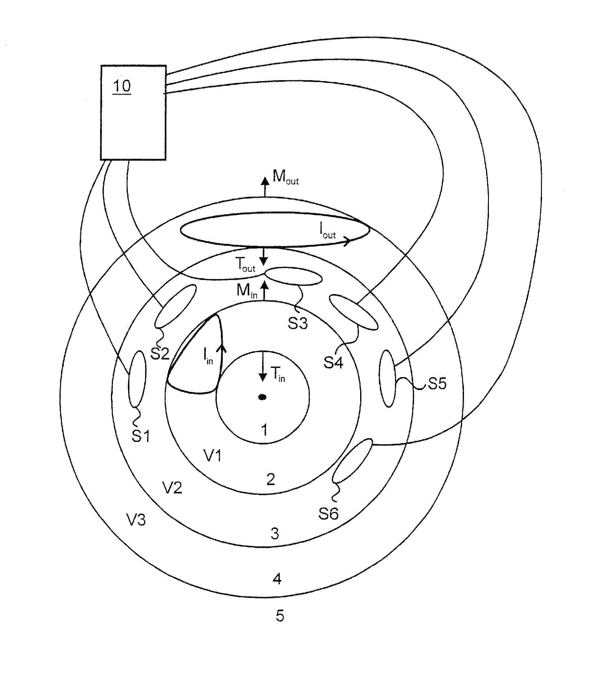
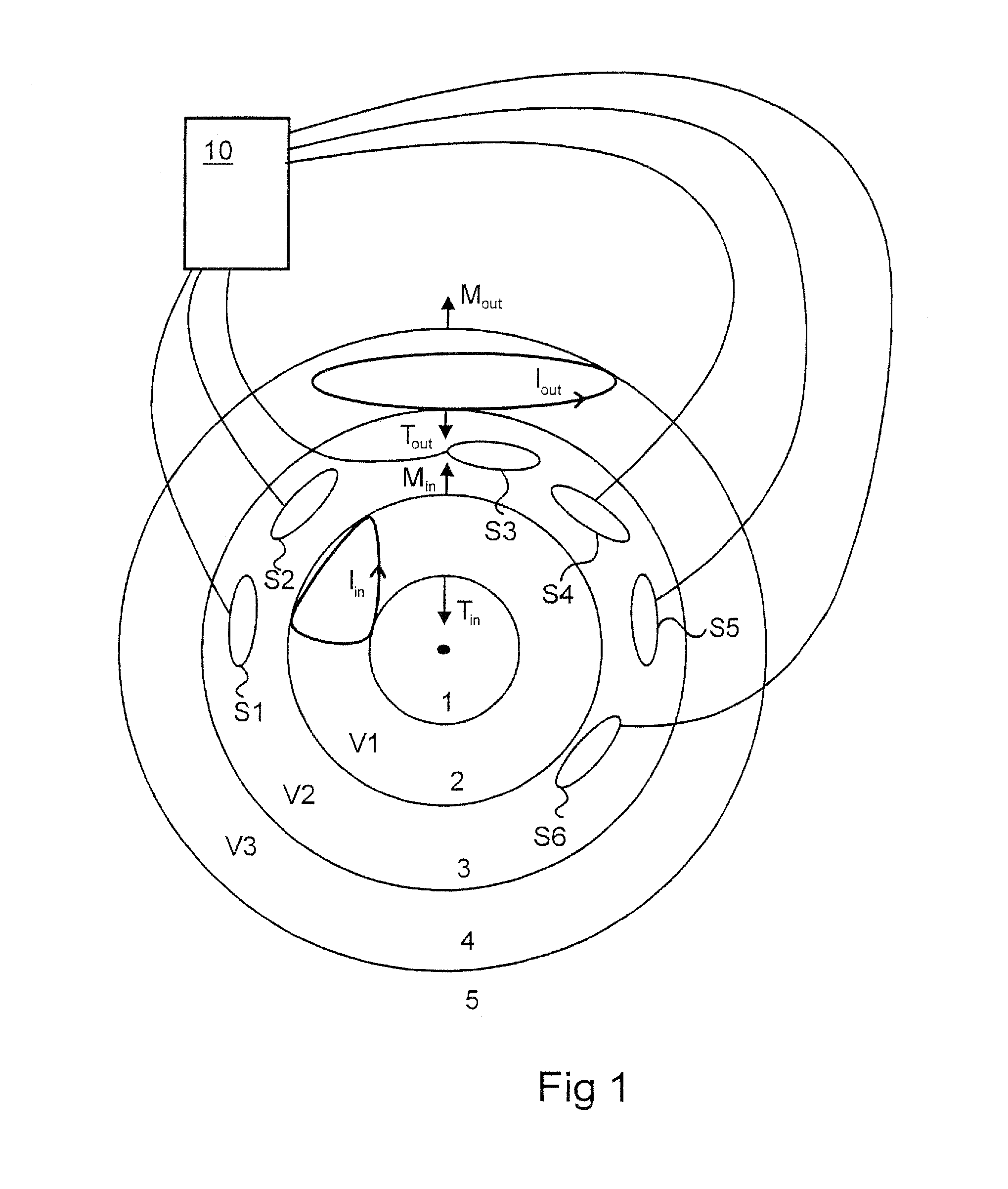
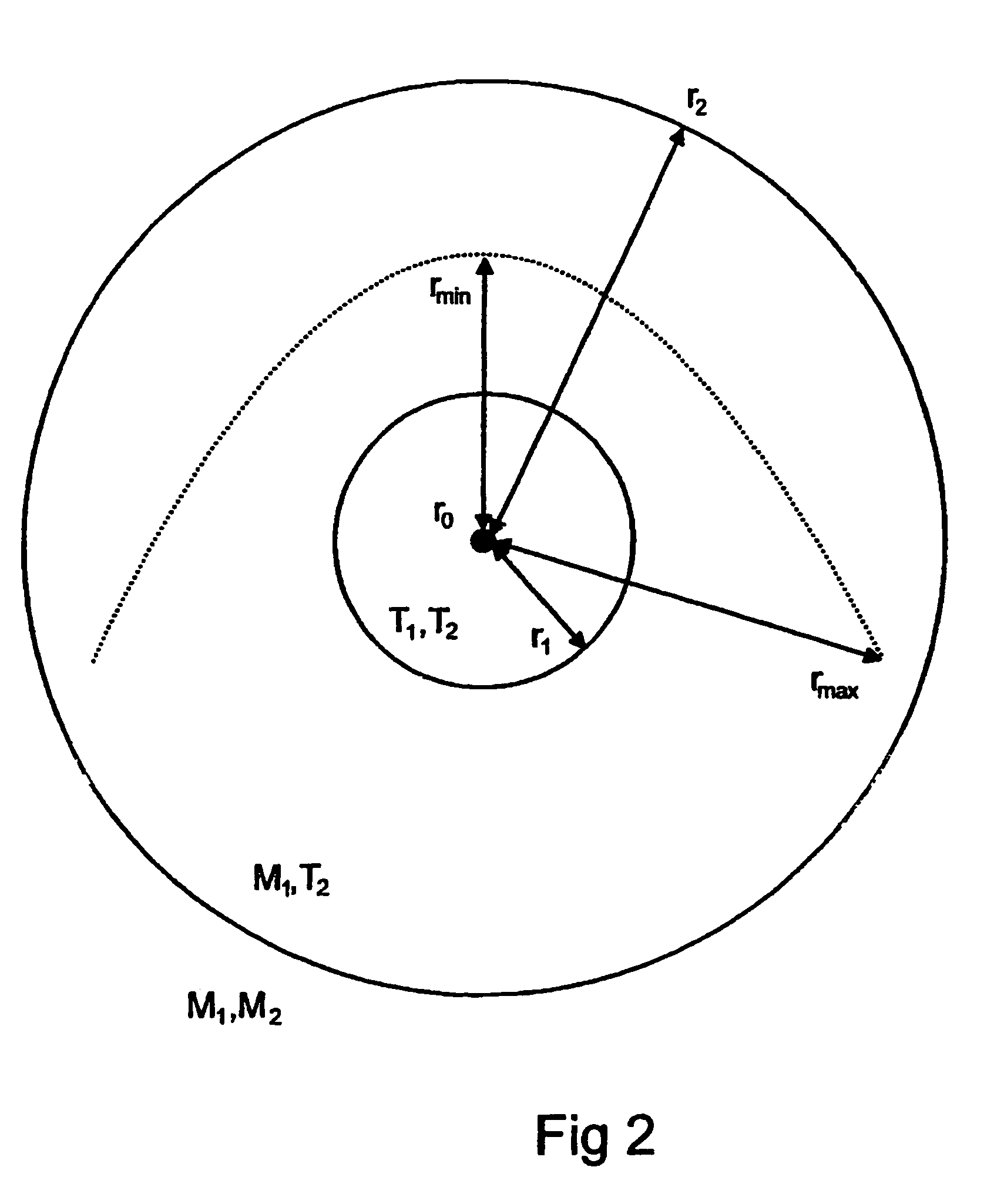
[0017]The invention is based on the utilisation of two different sets of vectors in the modeling of a signal that originates from two different sources. The requirement is that the vector field to be measured is irrotational and sourceless. The vectors of the signal space in question consist of vector field samples taken in different places of the physical space or of their linear combinations. In particular, the present invention relates to a method which is used to form such a basis in which the information contained in the whole vector field can be expressed with a number of basis functions as small as possible, in the selection of which one has taken into account the irrotationality and sourcelessness of the vector field. By means of the basis functions in question, the vector field can be represented in a form enabling a more enhanced, accurate and versatile mathematical operation of the field than before in many signal processing and analytical applications.

[0018]Furthermore, ...


PUM


Abstract

A method and device by means of which an irrotational, sourceless vector field can be expressed by a number of physically reasonable basis vectors. In the method and device for processing a multi-channel measurement of magnetic fields of the present invention, measured signals can be unambiguously divided into signals of the irrotational, sourceless vector field that are caused by an interesting object or external interferences, as well as into a signal caused by the nonideality of the measuring device. The invention is based on the combining of two very fundamental mathematical regularities and applying in the processing of signal vectors of a multi-channel measuring device that measures an irrotational, sourceless vector field. The invention is based on the Maxwell's equations of an irrotational, sourceless vector field, as well as on the convergence characteristics of series developments.

Description

FIELD OF THE INVENTION[0001]The present invention relates to a new and advanced method and system for processing a multi-channel measurement signal. In particular, the present invention relates to measurement geometry that measures a sourceless, irrotational vector field, which measurement geometry consists of a sensor arrangement; the invention also relates to the formation of a basis for signal space and the utilisation of the basis in the pre-processing and analysis of data measured by the measurement geometry.BACKGROUND OF THE INVENTION[0002]The representation of measurement signals or signal vectors measured by multi-channel measuring devices in some natural signal space basis is useful from the point of view of the analysis and illustration of the measured phenomenon. For example, in the case of a multi-channel magnetometer, one such basis can be obtained by modeling the source that produced the magnetic field by a current distribution whose total amplitude is the smallest pos...

Claims


Application Information

Patent Timeline
Patent Type & Authority Patents(United States)
IPC IPC(8): G01R33/02
CPCG01R33/02
Inventor SIMOLA, JUHAKAJOLA, MATTITAULU, SAMU
Owner MEGIN OY
Learn More