
Piezoelectric resonator with an efficient all-dielectric Bragg reflector

a bragg reflector and resonator technology, applied in the field of resonators, can solve the problems of large footprint on the wireless board, limited power handling capability, poor sensitivity to temperature and limited power, etc., and achieve high acoustic impedance, high efficiency, and high efficiency.

Active Publication Date: 2008-12-09
TEXAS INSTR INC
View PDF1 Cites 123 Cited by
  • Summary
  • Abstract
  • Description
  • Claims
  • Application Information

AI Technical Summary

Benefits of technology

[0011]Pursuant to the present invention, an SMR structure is disclosed which contains a highly efficient all-dielectric acoustic Bragg reflector. The dielectric materials that enable this type of reflector have unusually high acoustic impedances and belong to the family of silicon carbide (SiC), diamond-like-carbon (DLC) and silicon-doped-diamond-like-carbon (Si-DLC) refractory dielectrics. SiC has an acoustic impedance around 90% that of tungsten and almost a factor of 3 larger than aluminum nitride (AlN). Thus an impedance ratio of 7:1 can be obtained with a SiC / SiO2 reflector which compares very favorably with the 8:1 ratio afforded by a tungsten / SiO2 stack. The advantage of using SiC or other high acoustic impedance dielectric in the acoustic Bragg reflector is that a highly efficient reflector can be constructed with the minimum number of alternating layers.
[0012]Accordingly it is an aspect of the present invention to provide a method of manufacturing a Solidly Mounted Resonator (SMR) device. The SMR devices have less problems associated with packaging than an FBAR, but which do not suffer from the parasitic capacitance problems that are present in SMRs that utilize metal layers in the acoustic Bragg reflector. The SMR structure can be used as an all-dielectric acoustic Bragg reflector but at the same time can have as high an efficiency for the same number of layers as a metal / SiO2 acoustic Bragg reflector such as a W / SiO2 reflector.
[0014]It is yet another aspect of the present invention to provide an SMR structure that does not suffer from parasitic capacitive coupling with the substrate or other nearby resonators on the device.

Problems solved by technology

Ceramic filters are both high performance and low cost but they suffer from having a large footprint on a wireless board.
SAW filters exhibit size advantages over ceramic filters but suffer from a relatively poor sensitivity to temperature and a limited power handling capability.
BAW devices have a superior power handling capability compared to SAWs, are less sensitive to surface contamination, and have the potential for a very small footprint.
Although FBARs have excellent energy confinement because of the air gap, they are prone to spurious modes being superimposed on the fundamental resonance mode.
In addition, FBARs are difficult to manufacture particularly with regard to the packaging of such a structure.
If the materials used in the reflector have only a small difference in acoustic impedance then more alternating layers will be required to achieve the same performance, leading to higher device complexity.
However, there are drawbacks to incorporating a metal into the acoustic Bragg reflector.
Also, if silicon is used as a substrate, this can induce parasitic capacitive coupling between the resonator bottom electrodes and the substrate through the metal reflector layers.
Such coupling degrades the resonator's electrical performance.
However, due to the small difference in acoustic impedance between these two materials only a comparatively inefficient reflector can be constructed for the same number of alternating layers used in a metal / SiO2 stack such as W / SiO2.

Method used


Image

  • Piezoelectric resonator with an efficient all-dielectric Bragg reflector
  • Piezoelectric resonator with an efficient all-dielectric Bragg reflector
  • Piezoelectric resonator with an efficient all-dielectric Bragg reflector

Examples


Embodiment Construction

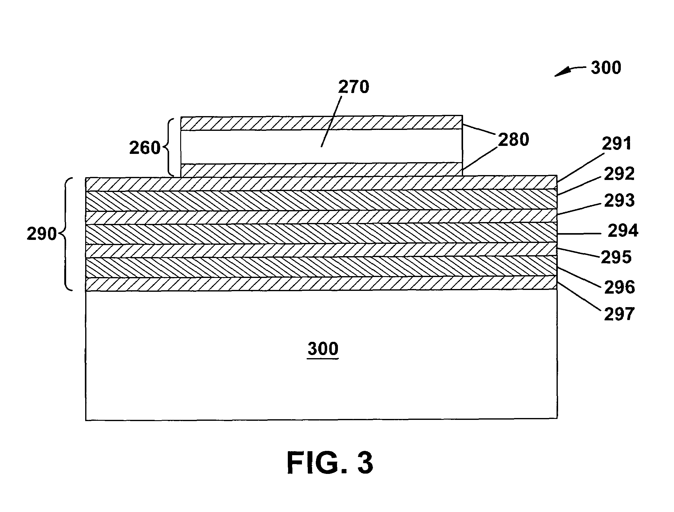
[0021]The following description of the embodiment below is merely an example and is in no way intended to limit the invention or its application or uses. The present invention discloses an SMR resonator device and a method for manufacturing an SMR resonator with a highly efficient all-dielectric acoustic reflector constructed with alternating layers of low acoustic impedance material such as SiO2 and high acoustic impedance material such as SiC, Si-DLC or DLC.

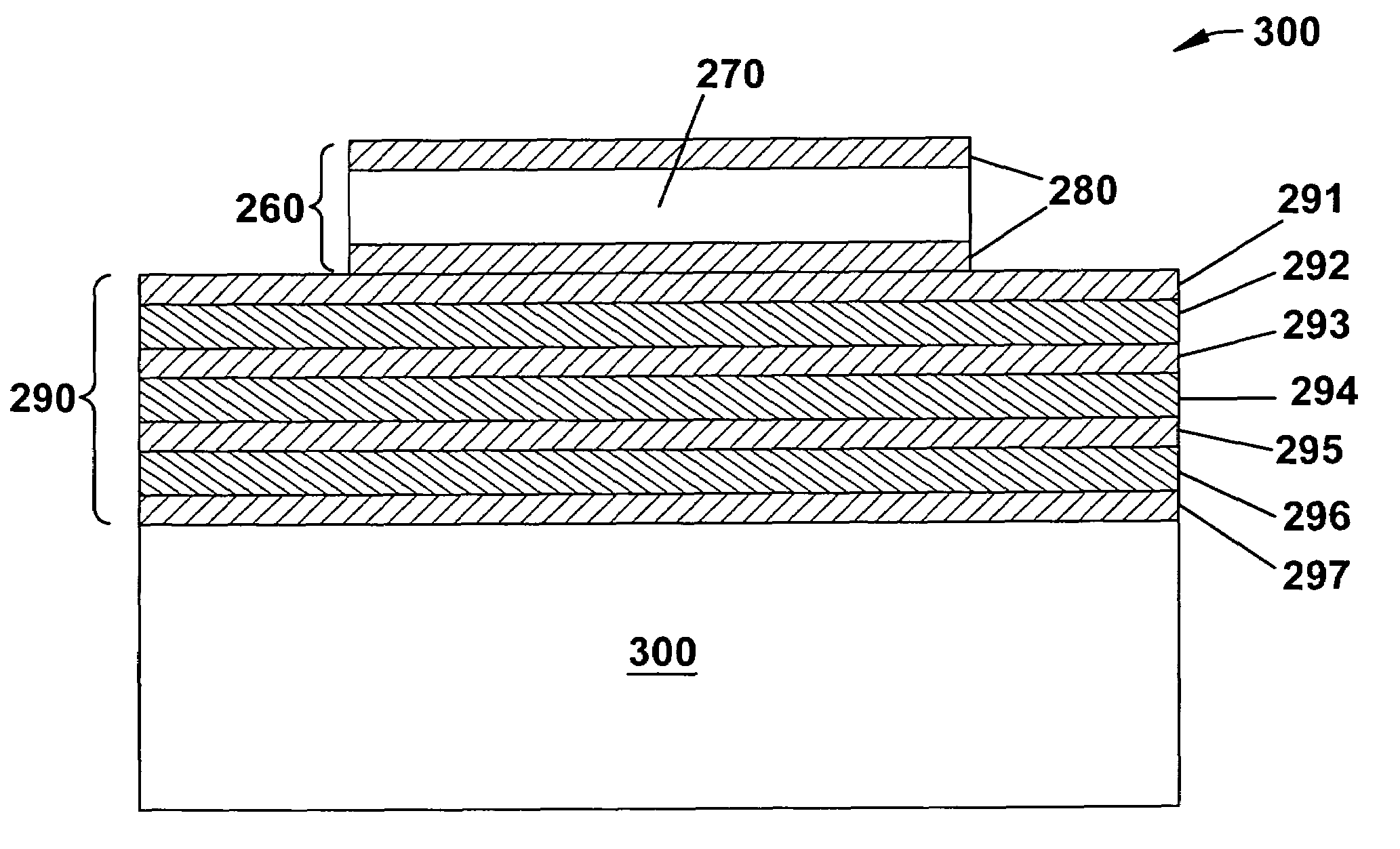
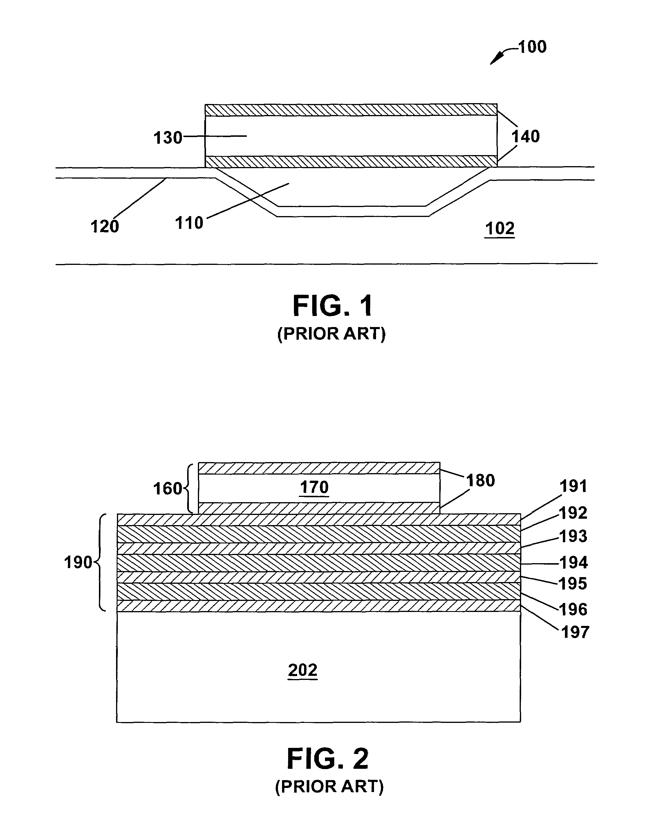
[0022]Referring to FIG. 3, the device begins with a suitable substrate such as a single crystal silicon wafer 300. A first layer of low acoustic impedance material 297 is deposited. In one example the low acoustic impedance material is nanoporous spin-on-glasses of nano-porous hydrogensilsesquioxane (HSQ) or nano-porous methyl silsesquioxane (MSQ) which is deposited in a spin coater with a subsequent curing step. A second layer of high acoustic impedance material 296 is then deposited on top of the first layer 297. If SiC is us...


PUM


Abstract

A piezoelectric resonator with an acoustic Bragg reflector that includes alternating layers of high and low acoustic impedance materials. The high and low acoustic impedance dielectric materials make up electrically insulating layers.

Description

TECHNICAL FIELD[0001]The present invention relates to a resonator device, and in particular to a resonator device incorporating a piezoelectric resonator accompanied by an acoustic Bragg reflector.BACKGROUND OF THE INVENTION[0002]Filters are utilized in RF electronic circuits in many important technological applications. In high volume applications such as wireless mobile telecommunications filter technologies today are dominated by Surface Acoustic Wave (SAW) and microwave ceramics. Ceramic filters are both high performance and low cost but they suffer from having a large footprint on a wireless board. SAW filters exhibit size advantages over ceramic filters but suffer from a relatively poor sensitivity to temperature and a limited power handling capability.[0003]The need to reduce cost and size in wireless equipment has led to a continuing need for even smaller and lower cost filters. One class of filter components that has the potential to meet these needs is based on Bulk Acoust...

Claims


Application Information

Patent Timeline
Patent Type & Authority Patents(United States)
IPC IPC(8): H03H9/15H01L41/08
CPCH03H3/04H03H9/175H03H2003/025
Inventor JACOBSEN, STUART M.
Owner TEXAS INSTR INC
Learn More