Dispenser head with a check valve

a technology of dispenser head and check valve, which is applied in the direction of lighting and heating apparatus, combustion types, instruments, etc., can solve the problems of dispenser head dirty, dispenser head still containing pressurized products, and small amount of still remaining in the delivery channel

Inactive Publication Date: 2008-12-16
RPC WIKO
View PDF11 Cites 22 Cited by
  • Summary
  • Abstract
  • Description
  • Claims
  • Application Information

AI Technical Summary

Benefits of technology

[0003]The objective of the invention is to design a dispenser head for pressurized dispensing contain

Problems solved by technology

A disadvantage of previously known dispensers or dispenser heads of this type is that after use and after the tilted upper part has returned to its initial position, the still pressurized product remaining in the delivery channel continues to emerge in s

Method used


Image

  • Dispenser head with a check valve
  • Dispenser head with a check valve
  • Dispenser head with a check valve

Examples


second embodiment

[0036]FIGS. 9 and 10 show the dispenser head of the invention. FIG. 9 shows the entire dispenser head 20 in its initial position, and FIG. 10 shows an enlarged section of the dispenser head 20 in its dispensing position. The dispenser head 20 consists of an upper part 30 and a lower part 31 with an integrated closure device 21. A valve body sleeve 28 with a valve body 25 inserted from the front and locked in place is arranged in the valve housing 24 of the closure device 21. To guide the valve body 25, the front part of the valve body sleeve 28 is formed with a nozzle head 36 with alternately arranged passages 36′ in a guide region 34 to allow the delivery of the product between the valve body 25 and the valve body sleeve 28. The valve body 25 is arranged in the valve body sleeve 28 in such a way that the valve head 27 closes the delivery hole 23 from the front. The valve body sleeve 28 is formed as part of the delivery channel 22 with a jacketed wall 32, which can be filled with th...

first embodiment

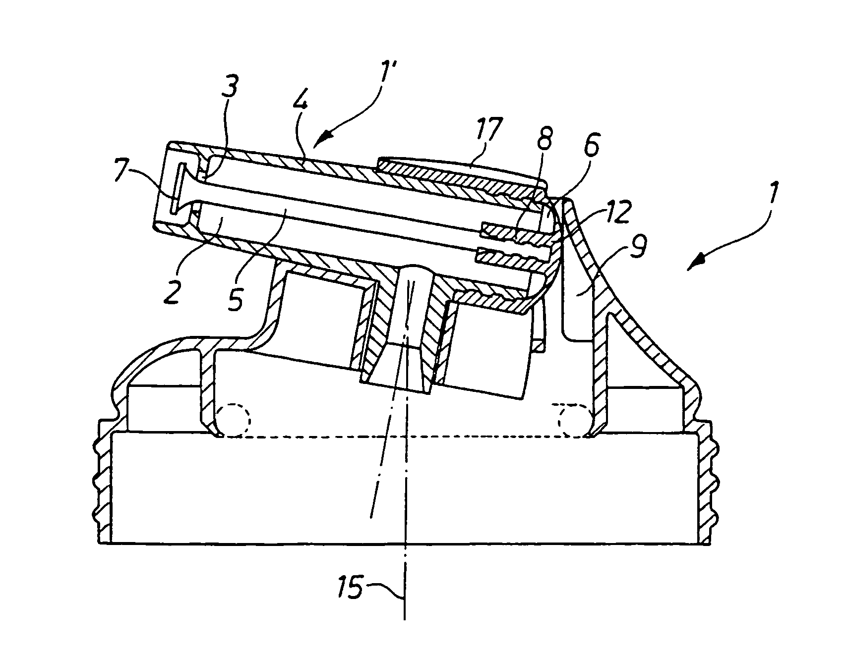
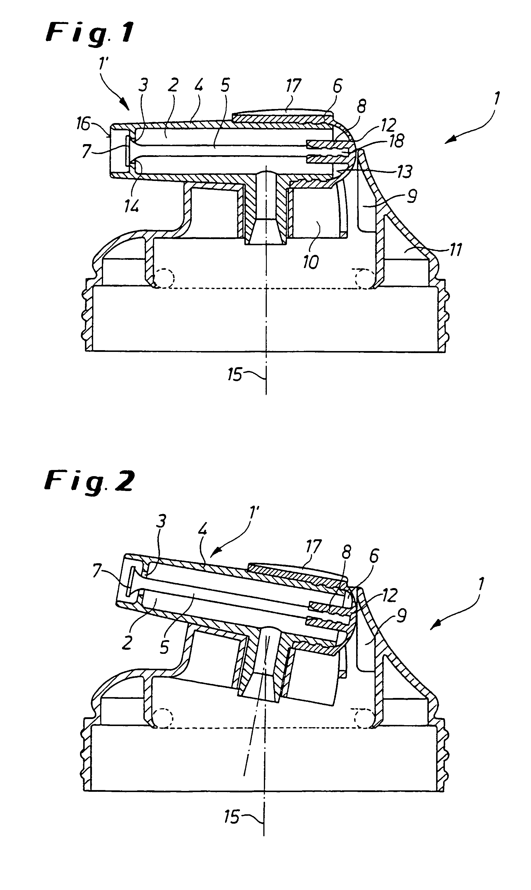
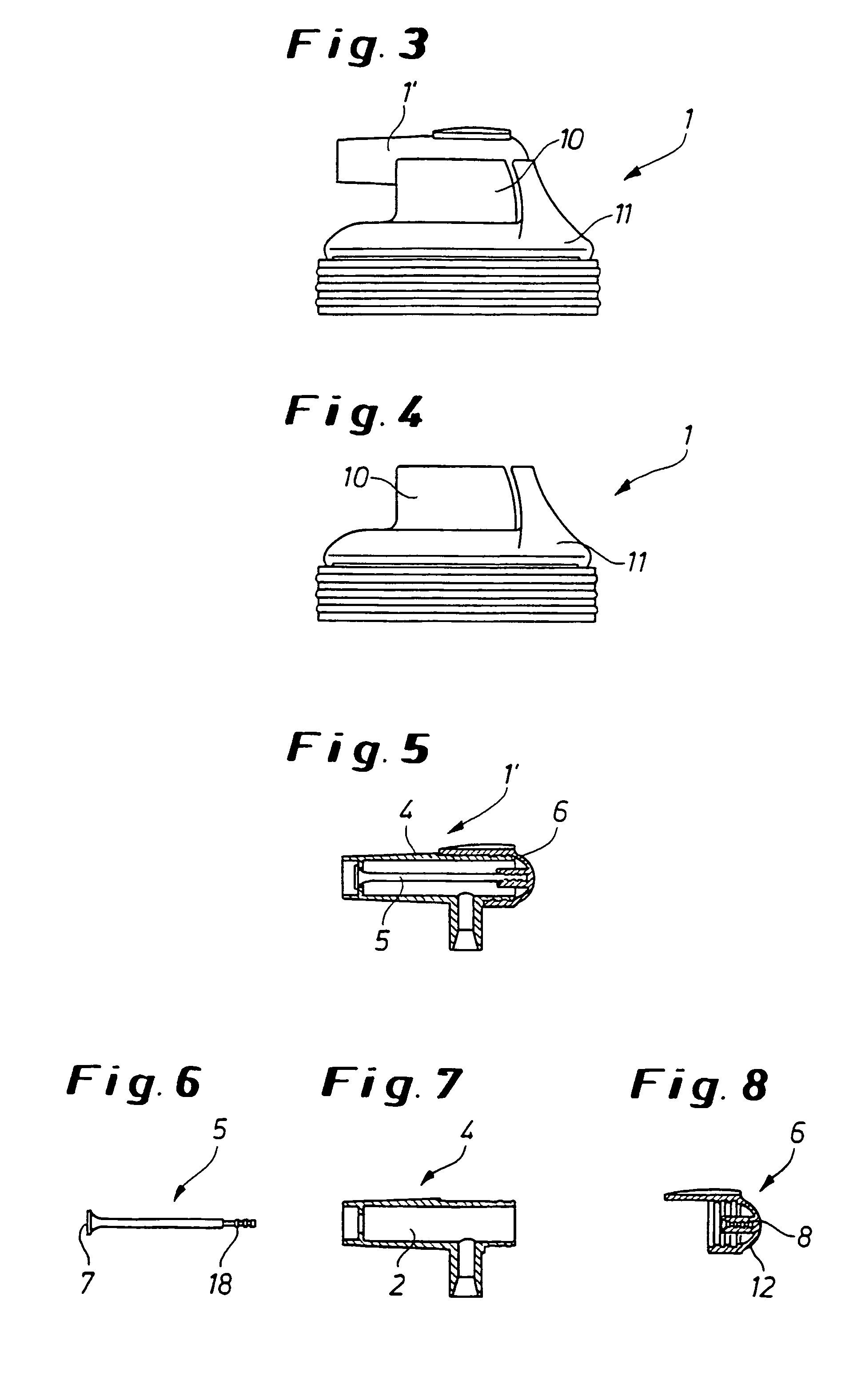
[0038]The function of the elastic dome 6 as a restoring element in the invention, which is illustrated in FIGS. 1 to 8, is performed in this second dispenser head 20 by the injected rear end 26 of the valve body sleeve 28. This rear end 26 consists of an elastic material and is permanently connected in a snap-in connection by the elastic annular beads 32′, 32″ with the upper part 30 and the lower part 31 of the dispenser head 20.

[0039]During the tilting movement of the closure device 21 by manual pressure on the button 37 to initiate the dispensing process, the valve body sleeve 28 with its restoring element or rear end 26 is moved in a circular path towards the stationary web 29 of the lower part 31 and pushed towards the front along with the valve body 25, so that the valve head 27 opens the delivery hole 23 towards the front, and the product emerges from the valve head 27 in the direction 39 indicated by the arrow. At the same time, the contact with the web 29 deforms (compresses...


PUM


Abstract

One disadvantage during delivery of products such as foams, for instance shaving foam or gel, self-foaming products and other products that are applied with a pressurized system from a conventional, pressurized dispenser container with the aid of known dispenser heads that can be inserted into the delivery valve of the dispenser container is that the pressurized product remaining in the delivery channel continues to be pressed out in small amounts in an uncontrolled manner after utilization despite the fact that the delivery valve is closed. In order to eliminate said disadvantage, the dispenser head (1) is configured with an additional closing device (1′) that automatically opens the delivery hole (3) and automatically closes it after the dispensing process is completed.

Description

BACKGROUND OF THE INVENTION[0001]The invention concerns a dispenser head with a delivery channel for delivering products, such as foams, for example, shaving cream or gel, self-foaming products, and other products that can be applied with a pressurized system, from a conventional pressurized dispensing container, wherein the dispenser head is mounted on the delivery valve of the dispensing container and opens the delivery valve of the dispensing container when external mechanical pressure applied to the dispenser head causes its upper part to tilt about a center of rotation, so that the product flows under pressure out of the delivery valve and into the delivery channel and is discharged from the dispenser head through the delivery hole of the delivery channel.[0002]A disadvantage of previously known dispensers or dispenser heads of this type is that after use and after the tilted upper part has returned to its initial position, the still pressurized product remaining in the deliver...

Claims


Application Information

Patent Timeline
IPC IPC(8): B65D83/28A45D27/10B05B1/30B05B9/04B65D83/16B65D83/40
CPCB05B1/3006B05B1/3073B65D83/206A45D27/10B65D83/7535B05B11/1053
Inventor HEUKAMP, WOLFGANG
Owner RPC WIKO
Why Eureka
Try Eureka