Low input torque rotor for vane pump

a vane pump and low input torque technology, applied in the direction of positive displacement liquid engines, piston pumps, liquid fuel engines, etc., can solve the problem of achieve the effect of reducing the shear force of the fluid and reducing the required input torqu

Inactive Publication Date: 2008-12-23
DANFOSS POWER SOLUTIONS INC
View PDF14 Cites 11 Cited by
  • Summary
  • Abstract
  • Description
  • Claims
  • Application Information

AI Technical Summary

Benefits of technology

[0008]The rotor has at least one non-smooth top or bottom surface. Specifically, in one embodiment, the top and bottom surfaces of the rotor are dimpled. Alternatively, the top and bottom surfaces of the rotor have slots, holes, pockets, or a shot peen pattern. As such, the non-smooth top and bottom surfaces introduce fluid turbulences across the rotor that reduce the shear force of the fluid against the rotor, thereby reducing the required input torque.

Problems solved by technology

As such, the non-smooth top and bottom surfaces introduce fluid turbulences across the rotor that reduce the shear force of the fluid against the rotor, thereby reducing the required input torque.

Method used


Image

  • Low input torque rotor for vane pump
  • Low input torque rotor for vane pump
  • Low input torque rotor for vane pump

Examples


Embodiment Construction

[0015]As used herein, those skilled in the art will appreciate that a vane-type fluid displacement unit encompasses both vane-type pumps and motors.

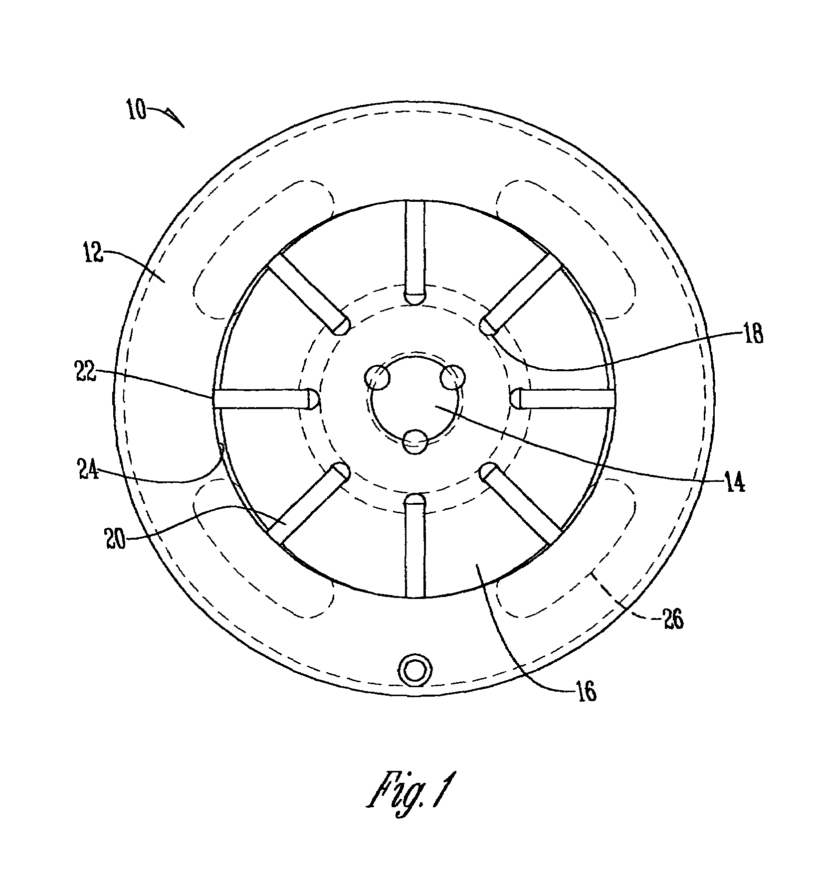
[0016]With reference to FIG. 1, a typical vane-type fluid displacement unit 10 is shown having a cam ring or housing 12, a drive shaft 14 extending through the housing 12, a rotor 16 secured to the drive shaft 14 and having slots 18 for receiving vanes 20. Fluid pressure within the slots 18 forces the vanes 20 radially outward such that the tips 22 of the vanes engage with the inner diameter 24 of the housing 12. In this manner, the vanes 20 sweep fluid compressed between the rotor 16 and inner diameter 24 of the housing 12 between inlet / outlet ports 26, as is well known in the art.

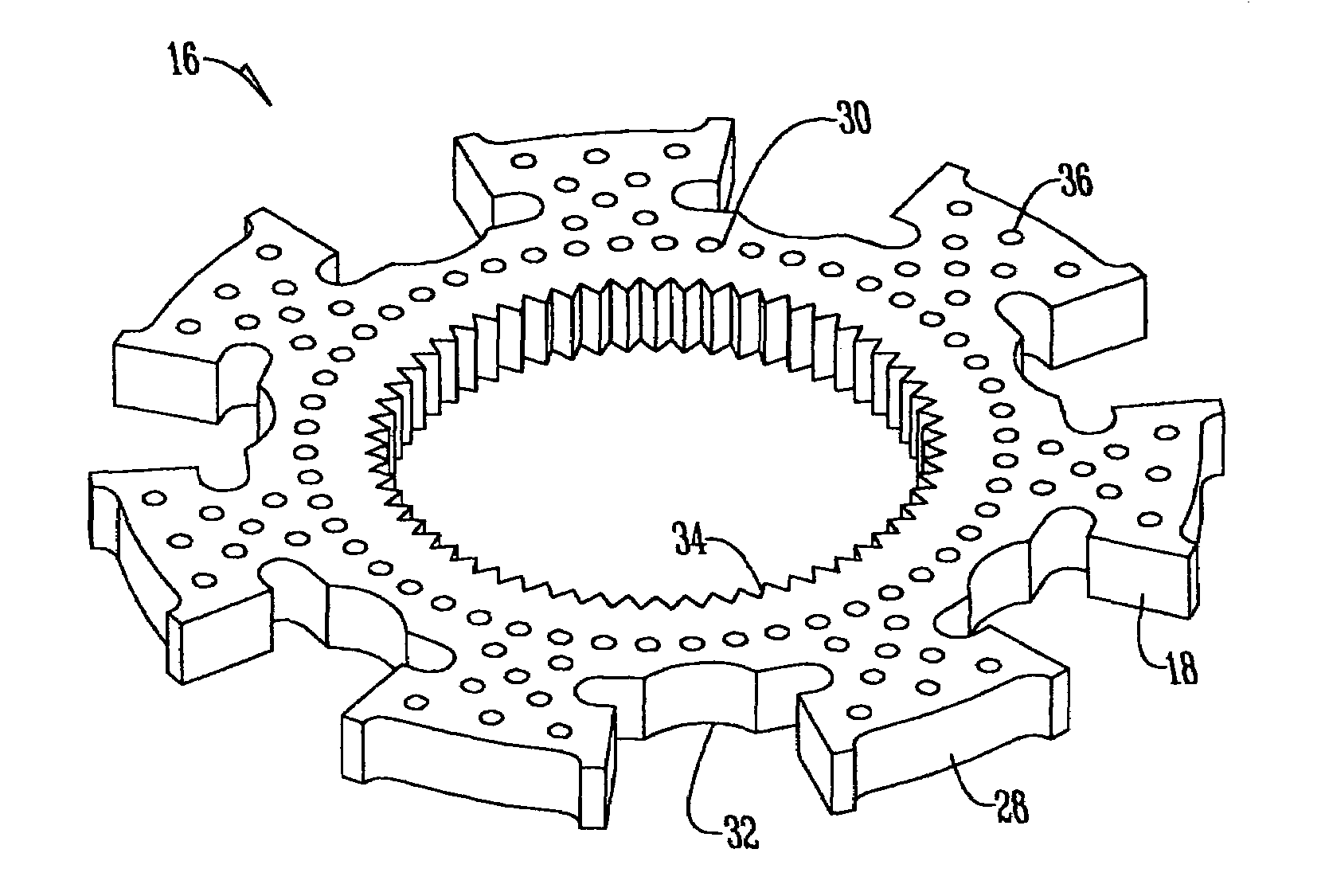
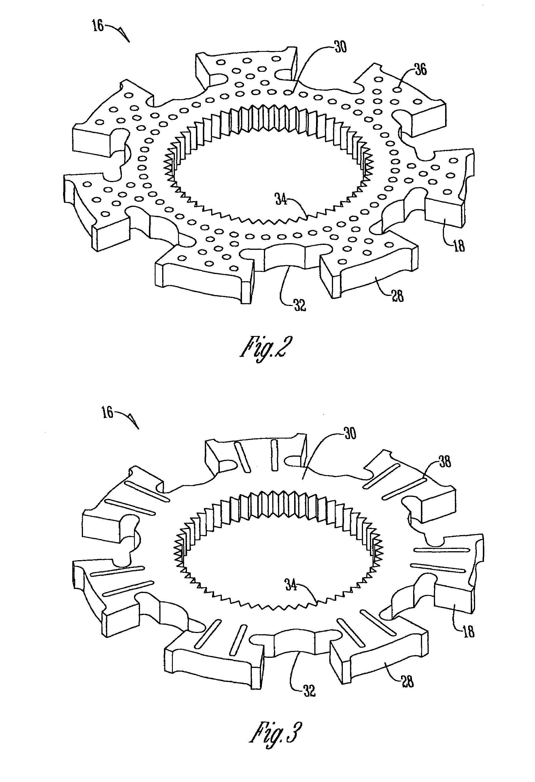
[0017]With reference to FIGS. 2-6, the rotor 16 is generally circular in shape with an outer side surface 28 and a top surface 30 opposite a bottom surface 32. Rotor 16 further includes a central aperture 34 to matingly receive the drive shaft 14. As shown in ...


PUM


Abstract

A vane-type fluid displacement unit having a housing, a drive shaft extending through the housing, a rotor secured to the drive shaft and disposed within the housing, the rotor having at least one non-smooth top or bottom surface, and at least one vane secured to the rotor.

Description

BACKGROUND OF THE INVENTION[0001]The present invention relates generally to fluid handling machines and, more particularly, to vane-type fluid displacement units having features of improved design.[0002]Vane-type fluid displacement units are well known in the art. One such example of a typical vane pump is disclosed in U.S. Pat. No. 6,503,064 to Croke et al., which discloses a rotor having smooth top and bottom surfaces. Typically, the top and bottom surfaces of rotors are ground smooth to a surface finish of Ra 4-20 micro inches. Because of the ground surfaces of the rotor, fluid passing through the vane pump exerts a shear force on the rotor, thereby requiring greater input torque.[0003]U.S. Pat. No. 5,560,741 to Edwards discloses a vane pump having a rotor with a trepanned or recessed portion centrally located on the top and bottom surfaces. The purpose of this recessed portion is to provide undervane fluid an escape path as the vanes move radially inward during rotation of the r...

Claims


Application Information

Patent Timeline
Patent Type & Authority Patents(United States)
IPC IPC(8): F03C4/00F04C18/00
CPCF01C1/3446F01C21/003F01C21/08
Inventor BETZ, MICHAEL ABRETEY, ERIC DKLINKEL, ROBERT JLANDHUIS, KEVIN J
Owner DANFOSS POWER SOLUTIONS INC
Why Eureka
Try Eureka