
Modular hip prosthesis

a hip and hip technology, applied in the field of modular hip prosthesis, can solve the problems of neck adjustment, neck impingement, and inability to individually alter or sized individual components, and achieve the effects of reducing range of motion, reducing leg length, and reducing component wear

Inactive Publication Date: 2008-12-23
ZIMMER INC
View PDF14 Cites 21 Cited by
  • Summary
  • Abstract
  • Description
  • Claims
  • Application Information

AI Technical Summary

Benefits of technology

[0018]One advantage of the present invention is that the stem, proximal body, and neck are all modular. These three components can be provided in a system wherein a plurality of differently sized and / or shaped stems, proximal bodies, and necks are provided. These components can be interchanged and removeably connected to each other to form a modular hip prosthesis. This modularity enables various stems, proximal bodies, and necks to be connected together to meet specific anatomical conditions encountered during a surgical procedure.
[0019]Another advantage of the present invention is that the hip prosthesis of the present invention offers a wide degree of adjustability between the stem, proximal body, and neck. This adjustability primarily occurs in three ways.
[0020]First, the neck is rotationally adjustable to an infinite number of positions about the stem. As such, the neck can be adjusted to match the natural femoral neck anteversion (forward rotation) that is widely variable from patient to patient. An inaccurate anteversion can cause a decrease in range of motion, neck impingement, excessive component wear, and lead to subluxation or even dislocation.
[0021]Second, the proximal body is both rotationally and axially adjustable to an infinite number of positions about the stem. This adjustability enables the proximal body to accurately fit within the intramedullary canal of the femur. The femur is basically shaped like a tube that is oval in cross section and that curves and twists along its length. When the proximal body is implanted at a high axial position in the femur, as in a primary surgery, a first degree of rotation is required. Conversely, when the proximal body is implanted at a low axial position in the femur, as in a revision surgery, a second degree of rotation (different than the first degree) is required. In short, the rotational and axial adjustability of the proximal body enable the surgeon to vary the shape of the hip prosthesis to suit the need of the patient. The combination of both axial and rotational adjustments provides a better fit between the proximal body and surrounding femoral bone. As such, bone may be saved and not cut to fit the shape or position of the proximal body.
[0022]Third, the st m is axially and rotationally adjustable once inserted inside the intramedullary canal of the patient. This adjustment occurs independent of the position of the proximal body in order to restore and obtain the proper leg length. For example, if the stem is inserted too far into the femur, then the leg length is shortened. On the other hand, if the stem is not inserted far enough into the femur, then the leg length is lengthened.
[0023]As another advantage of the present invention, the stem, proximal body, and neck are easily assembled and adjusted. Further, these three components can be disassembled if desired. Disassembly, for example, may be required if a component is replaced.

Problems solved by technology

Even though the implants are manufactured in a wide range of shapes and sizes, the individual elements cannot be separately altered or sized since no changes or adjustments occur between the elements themselves.
Some prior modular designs offer limited modularity between the individual, separate components.
Here, the neck has no adjustability since it is permanently affixed to the stem.
The neck is rotationally adjustable about an end of the stem, but the stem and proximal body are not adjustable.
Here, the proximal body and neck are rotationally adjustable but the proximal body is not axially adjustable along the stem.
Some prior modular designs also offer limited adjustability between the individual, separate components.
Prior hip prostheses, then, do not offer sufficient adjustability and modularity between the stem, proximal body, and neck.
This lack of adjustability and modularity limit the ability of the hip prosthesis to match various anatomical conditions encountered during a femoral surgical procedure.

Method used


Image

  • Modular hip prosthesis
  • Modular hip prosthesis
  • Modular hip prosthesis

Examples


Embodiment Construction

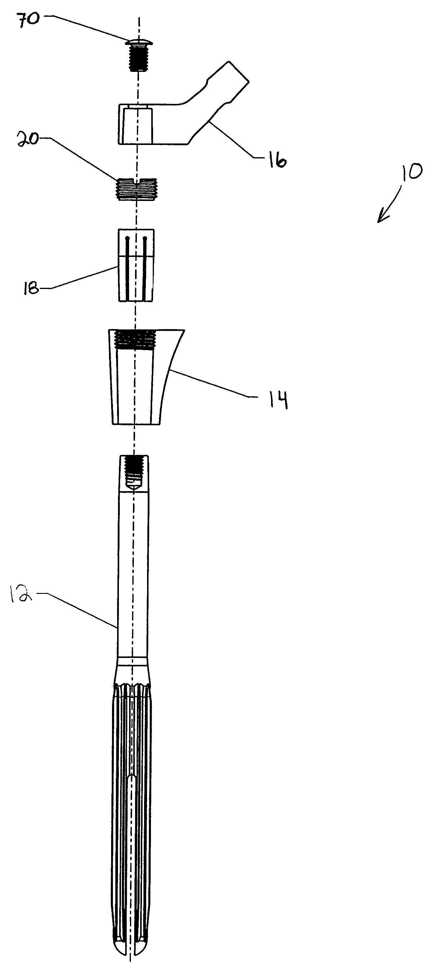
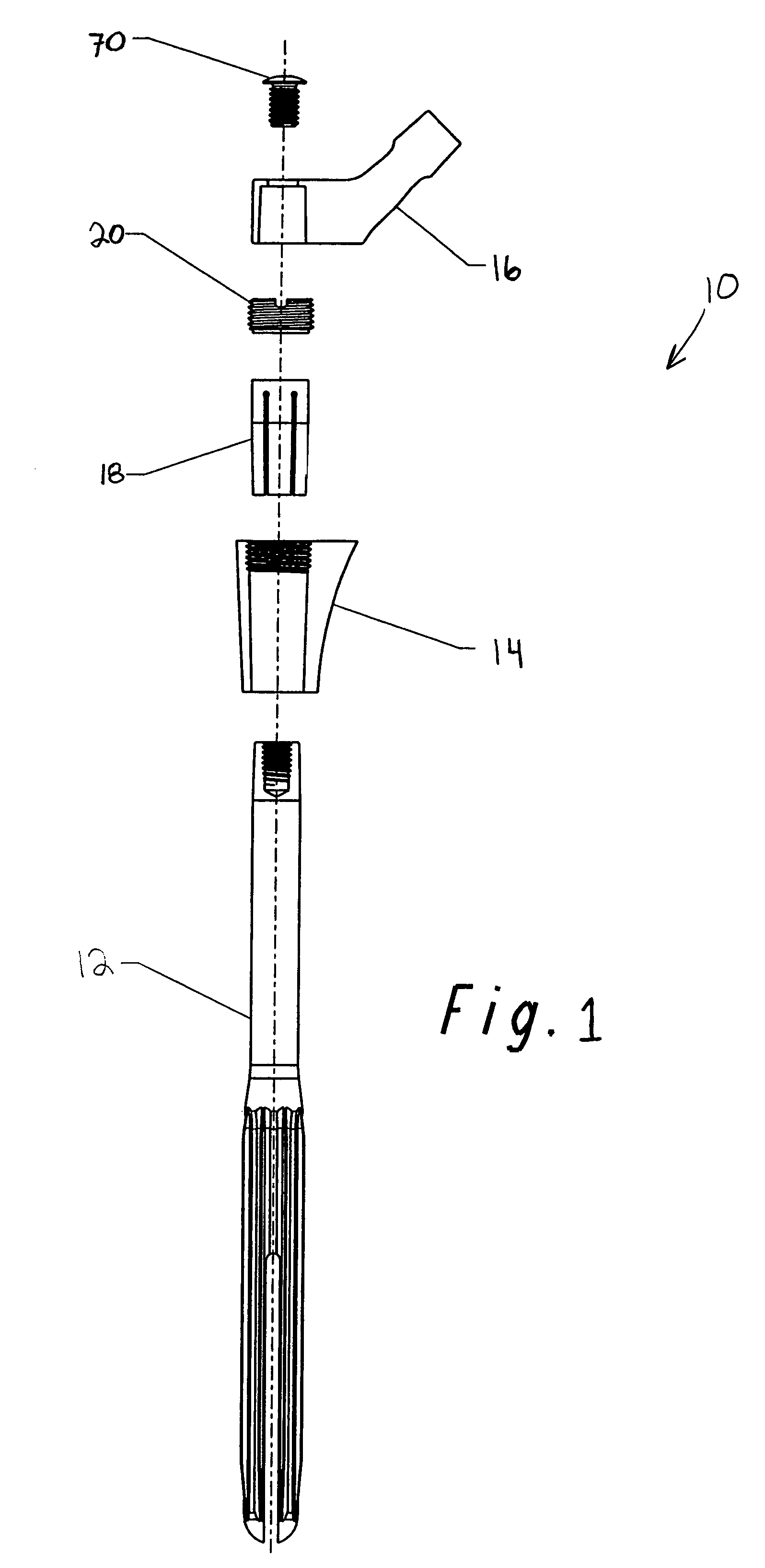
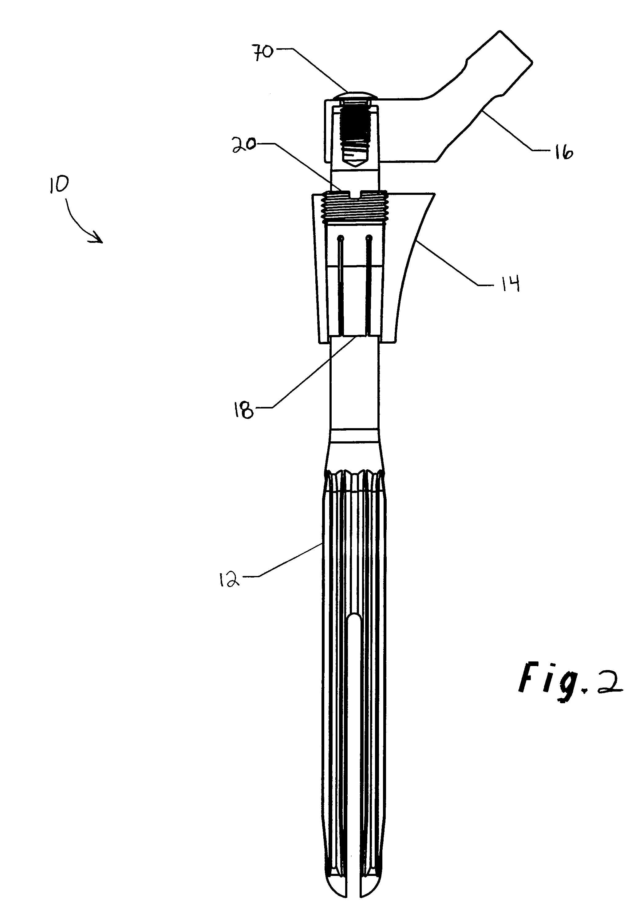
[0049]FIGS. 1 and 2 show a modular hip prosthesis 10 according to the invention. Prosthesis 10 generally includes three main components: a stem 12, a proximal body 14, and a neck 16. These components are adjustable with respect to one another and can be assembled and disassembled to form a modular prosthesis. As shown, a collet or sleeve 18 and a locking member 20 form a locking mechanism adapted to affix and lock the proximal body 14 to the stem 12.

[0050]Looking also to FIGS. 3A-3C, stem 12 is a separate component and has an elongated generally straight cylindrical body that extends from a proximal region 30 to a distal region 32. The proximal end includes a threaded cylindrical bore 34 that extends into the body. A locking or tapered surface 36 extends along the proximal region. This surface tapers radially inwardly toward the proximal end. An elongated, straight cylindrical section 38 is adjacent the locking surface 36. Section 38 has a smooth external surface and is adapted to r...


PUM


Abstract

A modular orthopedic hip prosthesis having three main components: a stem, a proximal body, and a neck. The components are removably connectable and selectively adjustable. The neck is rotationally adjustable about the stem, and the proximal body is both rotationally and axially adjustable about the stem. A collet and locking member hold and lock the proximal body to the stem.

Description

FIELD OF THE INVENTION[0001]The disclosure generally relates to implantable orthopedic prostheses for total hip replacement and, more particularly, to a modular hip prosthesis having interchangeable stems, proximal bodies, and necks that are selectively adjustable to conform to various anatomical conditions encountered during a femoral surgical procedure.BACKGROUND OF THE INVENTION[0002]In hip replacement surgery, the natural head and neck portion of the femur are removed and replaced with a metallic hip prosthesis. This prosthesis generally comprises three elements: a distal stem portion for fixation into the distal part of the femur, a proximal body portion for fixation in the metaphysis of the femur, and a neck portion for replacing the natural femoral neck. These elements can be connected and configured in numerous ways, but generally these elements form either a one-piece prosthetic hip design or a modular prosthetic hip design.[0003]One-piece designs are typically formed from ...

Claims


Application Information

Patent Timeline
Patent Type & Authority Patents(United States)
IPC IPC(8): A61F2/36A61F2/32A61F2/00A61F2/02A61F2/30A61F2/46
CPCA61F2/30734A61F2/36A61F2/367A61F2/3676A61F2002/30092A61F2002/30143A61F2002/30217A61F2002/30224A61F2002/30235A61F2002/30332A61F2002/30354A61F2002/30405A61F2002/30433A61F2002/30474A61F2002/30497A61F2002/30512A61F2002/30542A61F2002/30553A61F2002/30596A61F2002/30598A61F2002/30604A61F2002/30616A61F2002/30738A61F2002/30774A61F2002/30795A61F2002/30797A61F2002/30827A61F2002/30879A61F2002/30891A61F2002/3625A61F2002/365A61F2002/3652A61F2002/366A61F2002/3696A61F2002/4638A61F2210/0014A61F2220/0025A61F2220/0033A61F2220/0041A61F2230/0017A61F2230/0067A61F2230/0069A61F2250/0008A61F2310/00017A61F2310/00023A61F2310/00029A61F2002/30495A61F2002/30507A61F2002/3054A61F2002/30594
Inventor SEDERHOLM, GARYELY, SCOTTGUSTKE, KENNETHPLASTER, RODNEYTISCHLER, HENRY
Owner ZIMMER INC
Learn More