
System and method for detecting noise source in a power line communications system

a technology of power line communication system and noise source, applied in the field of data communication, can solve problems such as insulator failure, buzz noise prediction of failure, and noise generated by the various components of electrical distribution system

Active Publication Date: 2008-12-23
CHEMTRON RES
View PDF47 Cites 229 Cited by
  • Summary
  • Abstract
  • Description
  • Claims
  • Application Information

AI Technical Summary

Benefits of technology

"The present invention provides a way to detect information about the type and location of noise sources in a power line communication system. This can help to improve the quality of the communication and to identify the source of the noise."

Problems solved by technology

A common problem encountered during data communication in PLCSs is noise generated by the various components of the electrical distribution system.
Buzz noise is generally due to micro-sparks, corona discharge or partial discharge mechanisms in insulators as a result of the voltage potentials applied by the electric utility.
This noise tends to be localized to the source.
Additionally, buzz noise may be predictive of failure of one or more parts of the electric utility network.
For example, for overhead power lines such as medium voltage power lines, insulator failure may be result from wear, weather factors, vegetation contact and other causes.
One method for locating noisy insulators involves physical surveys, but such surveys are difficult and frequently non-productive since fully quantitative noise measurements are almost impossible with simple, portable equipment that can be operated by utility line personnel.
No quantitative and systematic method exists today that allows large areas of the electric utility infrastructure to be monitored for RF noise.

Method used


Image

  • System and method for detecting noise source in a power line communications system
  • System and method for detecting noise source in a power line communications system
  • System and method for detecting noise source in a power line communications system

Examples


Embodiment Construction

[0013]In the following description, for purposes of explanation and not limitation, specific details are set forth, such as particular methods, process steps, networks, communication systems, computers, terminals, devices, PLCSs, components, techniques, data and network protocols, software products and systems, operating systems, development interfaces, hardware, etc. in order to provide a thorough understanding of the present invention.

[0014]However, it will be apparent to one skilled in the art that the present invention may be practiced in other embodiments that depart from these specific details. Detailed descriptions of well-known networks, communication systems, PLCSs, computers, terminals, devices, components, techniques, data and network protocols, software products and systems, operating systems, development interfaces, and hardware are omitted so as not to obscure the description of the present invention.

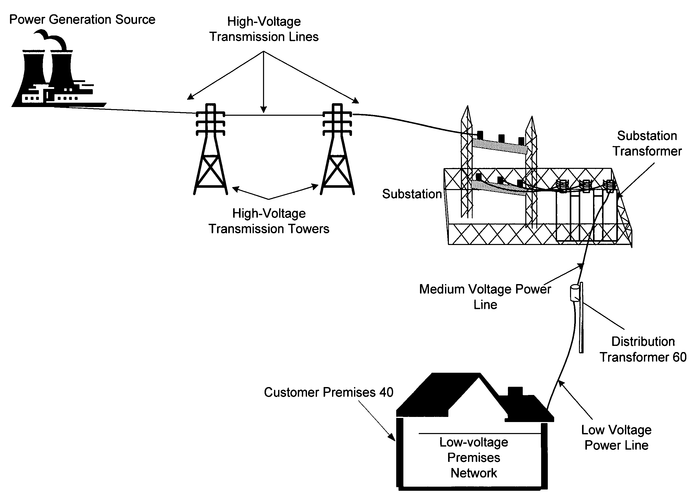
[0015]As shown in FIG. 1, power distribution systems typically includ...


PUM


Abstract

A method for detecting noise location information in a power line distribution system is disclosed. In one embodiment, the method includes the steps of receiving link quality data for a first power line communication link between a first and second power line communications device, determining an asymmetry in the link quality data of the link, and determining location information for the noise source based on the location of the first power line communications device or the location of the second power line communications device.

Description

FIELD OF THE INVENTION[0001]The present invention generally relates to data communications over a power distribution system and more particularly, to a system and method for determining information of the location of a noise source in power line communications systems.BACKGROUND OF THE INVENTION[0002]Well-established power distribution systems exist throughout most of the United States, and other countries, which provide power to customers via power lines. With some modification, the infrastructure of the existing power distribution systems can be used to provide data communication in addition to power delivery, thereby forming a power line communication system (PLCS). In other words, existing power lines that already have been run to many homes and offices can be used to carry data signals to and from the homes and offices. These data signals are communicated on and off the power lines at various points in the power line communication system, such as, for example, near homes, offic...

Claims


Application Information

Patent Timeline
Patent Type & Authority Patents(United States)
IPC IPC(8): G08B1/08
CPCH04B1/1027H04B3/542H04B15/00H04L25/085H04B2203/5441H04B2203/5445
Inventor YANEY, DAVID STANLEY
Owner CHEMTRON RES
Learn More