Multiway valve

a multi-way valve and valve body technology, applied in the direction of mechanical equipment, transportation and packaging, service pipe systems, etc., can solve the problems of serious harm to the health of patients, inability to adapt to the use of different types of valves, and certain drawbacks and/or operational limitations of known techniques summarized above, so as to maintain maximum reliability of the device and keep costs low

Active Publication Date: 2008-12-30
FRESENIUS MEDICAL CARE DEUTSCHLAND GMBH
View PDF38 Cites 69 Cited by
  • Summary
  • Abstract
  • Description
  • Claims
  • Application Information

AI Technical Summary

Benefits of technology

[0022]A first object of the invention is to provide a flow shut-off element which is as versatile and adaptable as possible.
[0023]A further object of the invention is to maintain maximum reliability of the device without essentially detracting from the intrinsic simplicity of construction of the known devices, and while also keeping the costs low, in view of the fact that the valves to which the invention relates are generally of the disposable type.
[0024]A subsidiary object of the invention is to provide a shut-off element in which the correct sequence of operations is made compulsory, in such a way that a user cannot inadvertently carry out these operations in an incorrect temporal sequence.

Problems solved by technology

Clearly, since manual opening and closing operations have to be performed on the tubing, a degree of experience and attention is required from the user who might otherwise make mistakes in the sequence of stages, or even carry out incorrect operations which could result in serious harm to the patient's health.
However, the known technique summarized above has certain drawbacks and / or operational limitations.
In the first place, the valves of the known type described above have no versatility at all, and are difficult to adapt.
Furthermore, with the aforementioned shut-off element it is not possible to specify the sequence of successive operations which the valve is to perform; in particular, the operator only has the sensation of correct positioning in the various operating conditions, but there is no indication as to the correctness of the valve opening / closing sequence being executed by the device.

Method used


Image

  • Multiway valve
  • Multiway valve
  • Multiway valve

Examples


Embodiment Construction

[0042]With reference to the aforesaid figures, the number 1 indicates the whole of a flow shut-off element for use, in particular, in medical applications, and more particularly in circuits for peritoneal dialysis.

[0043]As shown in FIG. 14, the shut-off element 1 is designed to operate (as explained more fully below) in the area of the junction of the infusion line 100 and the drain line 200 with the inlet line 300 leading to the patient's peritoneal cavity.

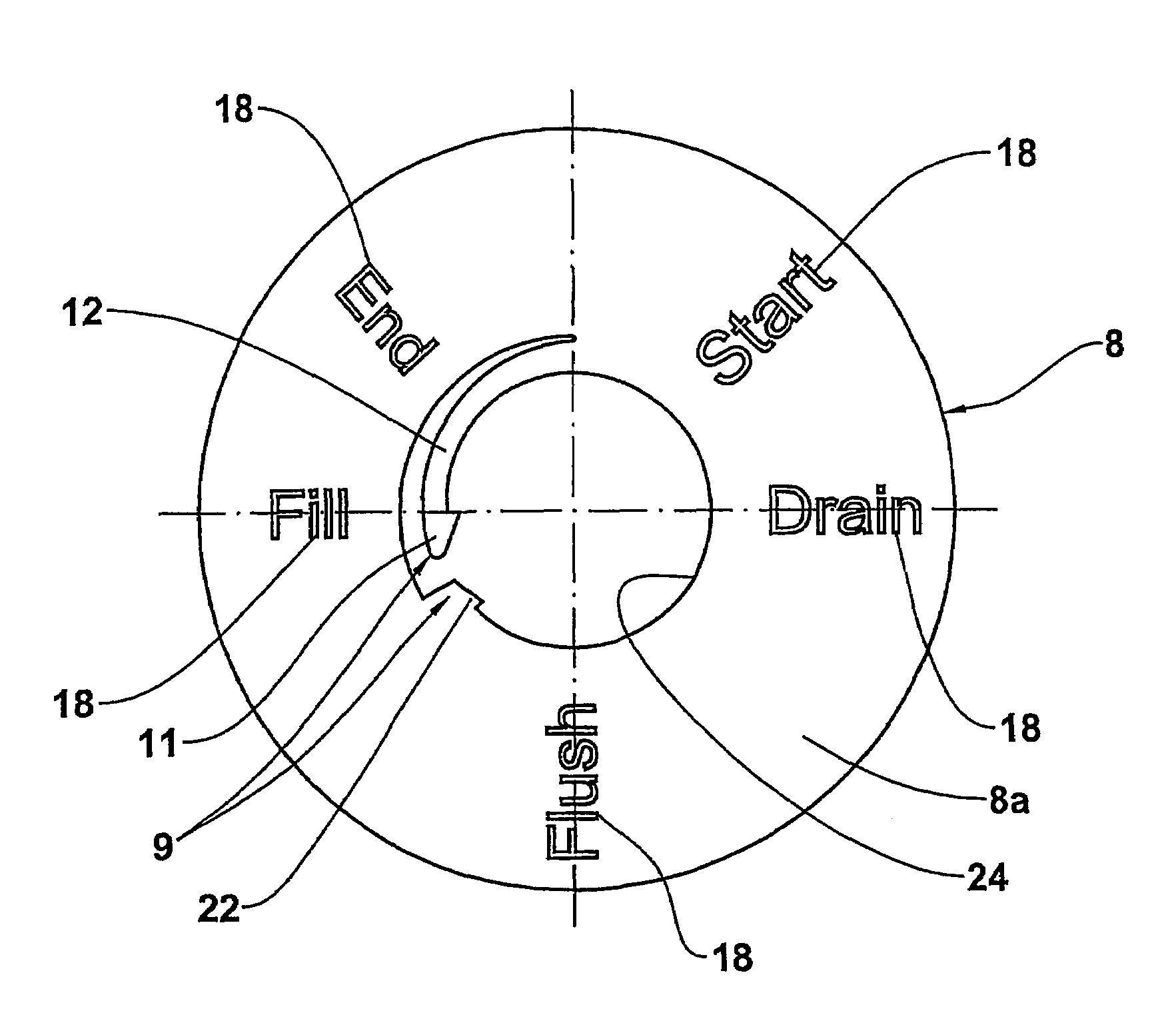
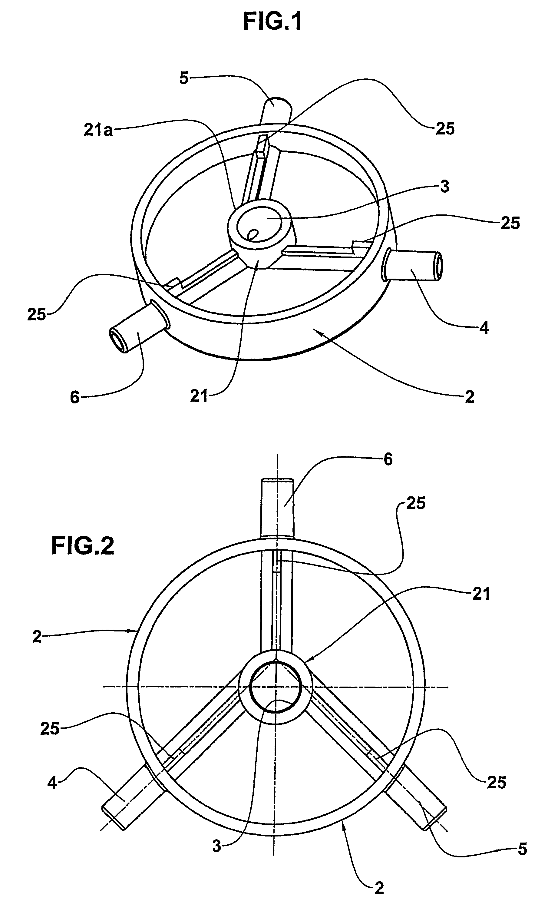
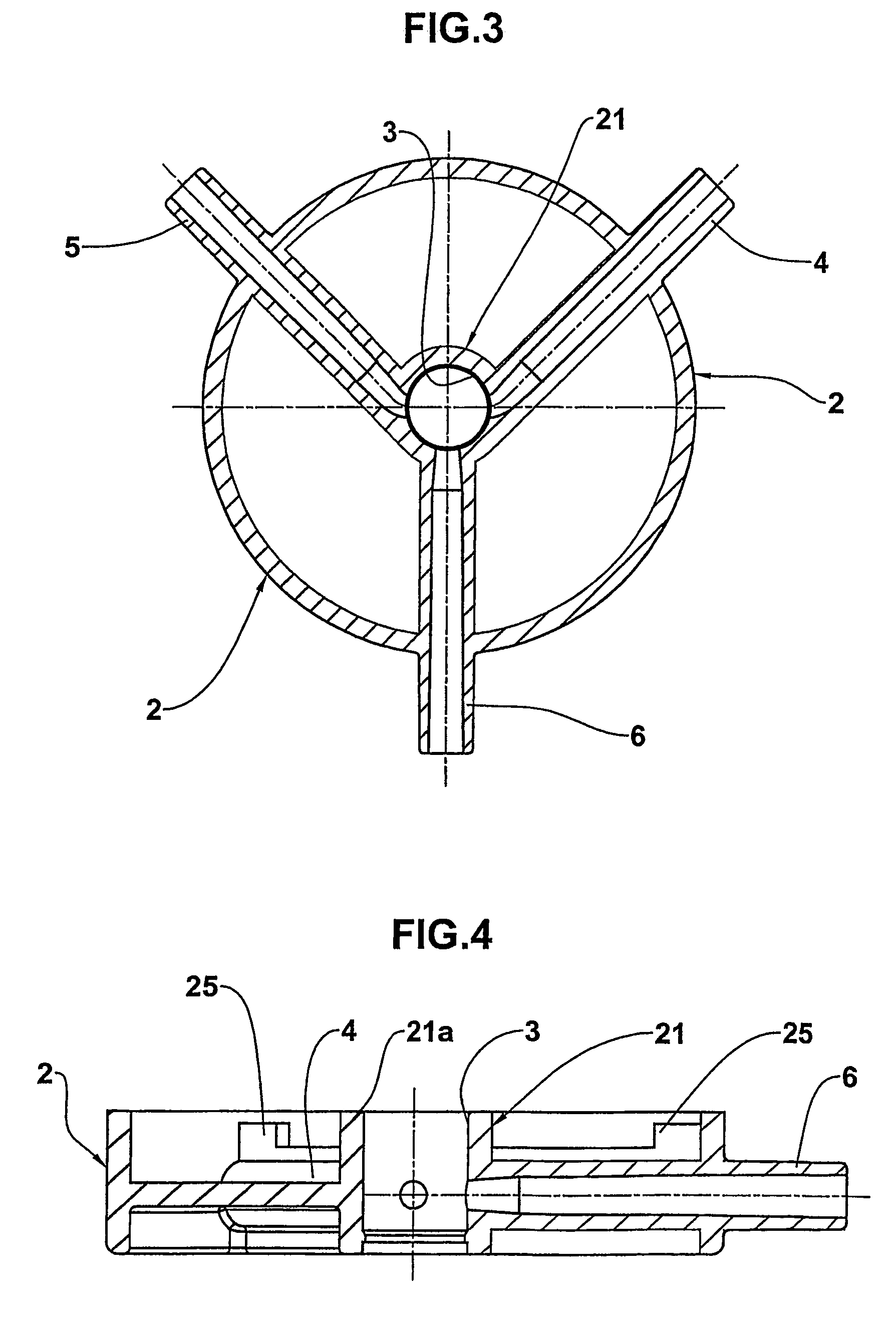
[0044]To provide greater structural detail, it can be seen that the shut-off element consists of a valve body 2 (see FIGS. 1 to 4) which has an essentially discoid profile and has a plurality of accesses 4, 5 and 6, of which there are three in this particular case, designed to be connected, respectively, to the infusion line 100, to the drain line 200, and to the patient line 300.

[0045]In particular, the terminal portions of the tubes forming the aforementioned lines are engaged with the projecting portions of these accesses and ...


PUM


Abstract

What is provided is a flow shut-off element, particularly for use in the medical field of peritoneal dialysis, consisting of a valve body (2) having an inner cavity (3) and a plurality of accesses (4, 5, 6); a selector having a projecting portion inserted into the inner cavity of the valve body and movable relatively to the latter into a predetermined number of operating positions to create predetermined paths in which the fluid flow is permitted and / or shut off between the said accesses. Also provided is an auxiliary element interposed in a removable way between the valve body and the selector, this element having positioning means to enable an operator to determine when one of the said predetermined operating positions of the selector has been reached.

Description

CROSS REFERENCE TO RELATED APPLICATIONS[0001]This application is an national phase application based on PCT / IB2003 / 003166, filed Aug. 5, 2003, the content of which is incorporated herein by reference, and claims the right to priority based on Italian Application No. MI2002A001895, filed Sep. 6, 2002.BACKGROUND OF THE INVENTION[0002]The present invention relates to a flow shut-off element.[0003]In particular, the flow shut-off element according to the present invention is intended for applications in the medical field and, in greater detail, this device can be used in circuits for peritoneal dialysis.[0004]As is known, a circuit for peritoneal dialysis consists of at least one tube connected to the patient's peritoneal cavity; in practice, the tube consists of a surgically implanted fixed catheter having an outlet inside the peritoneal cavity, and a portion outside the body to which is connected a further length of tubing designed to be replaced periodically.[0005]The circuit thus ha...

Claims


Application Information

Patent Timeline
Patent Type & Authority Patents(United States)
IPC IPC(8): F16K37/00F16K11/074A61M1/14A61M1/28A61M39/22
CPCA61M39/223A61M1/28Y10T137/8275Y10T137/8359Y10T137/86863A61M39/22A61M39/00
Inventor PARRINO, ANDREABULGARELLI, CESARE
Owner FRESENIUS MEDICAL CARE DEUTSCHLAND GMBH
Why Eureka
Try Eureka