Roll support device for continuous metallic strip casting

a technology of supporting device and metallic strip, which is applied in the direction of ingot mould roll support device for continuous metallic strip casting, which can solve the problems of compromising the roll assembly itself, affecting the symmetry or planarity of the strip thickness, and requiring a large investment of resources, so as to avoid the lack of symmetry or planarity defects of the strip thickness

Inactive Publication Date: 2006-09-05
DANIELI & C OFF MEC SPA
View PDF6 Cites 4 Cited by
  • Summary
  • Abstract
  • Description
  • Claims
  • Application Information

AI Technical Summary

Benefits of technology

[0015]It is therefore an object of the present invention to solve the above-mentioned problems by providing a support device which ensures the maximum reliability during the continuous metallic strip casting, an evenly thick strip, and which can be used in the presence of high temperature, and allows for the required displacement of the rolls with coordinate and sufficiently precise movements of the supports of the two opposite ends of each roll, to avoid lack of symmetry or planarity defects of the strip thickness. Such problems are solved according to claim 1 by support device on a assembly of a first and a second cooled casting rolls with a pair of plates abutted on each end of said pair of rolls, working as a mould for continuous metal strip casting, said first and second rolls having parallel axes and each of them being supported by at least one movable support element near to the axial ends, said movable support elements being suitable for allowing a mutual movement of approaching and distancing of said rolls of said pair, each movable support element associated with the first roll being connected to said assembly by means of its respective hydraulic actuator suitable for thrusting said first roll in the direction of said second roll and suitable for thrusting each support element against an abutting end element, each movable support element associated with the second roll being connected to said assembly by a magnetostrictive actuator and a load cell suitable for making said second roll perform movements of mutual approaching and distancing from said first roll, wherein a bar of the magnetostrictive actuator is provided with a preloading system and between each movable support element and said assembly there is provided at least one respective hydraulic bearing suitable for allowing sliding movement of each of said movable support elements with respect to said assembly.
[0017]Owing to the innovative characteristics of the present invention the roll supports, made by providing the hydrostatic bearings ensuring a fluid film between the rolls themselves and the support platform, reduce a lot the friction coefficient in the support. Such solution allows one to obtain better results also for use near to a heat source at a high temperature.
[0018]The casting process is kept to an optimal level thanks to the characteristics of the supports, which during the movement in the direction of mutual distancing and approaching of the rolls present a minimum friction both between the roll supports and the stationary frame of the box and between the joint for the feeding and draining the roll cooling water. The friction minimization obtained with the support device of the present invention is also important to ensure a symmetric process, otherwise different conditions can occur to the same roll with two different supports and the cast strip will consequently have a variable thickness along its width.

Problems solved by technology

These operating methods involve very expensive plants and notable expenditure of energy.
The casting rolls are one of the most complex parts of the casting line, since they must comprise, inter alia, a cooling system for the rolls themselves, and a delicate support system, which must also allow for, inter alia, the cast strip thickness adjustment.
A problem to be solved in the plants of this type is that of ensuring movements of approaching and removal which are as quick as possible also to face emergency conditions, such as when a quick and almost immediate distancing of the rolls is required to drop the molten metal which is still upon the rolls.
Another problem to be solved is that of improving the reliability of the supports to minimize the danger of seizure in operation, which may compromise the roll assembly itself with serious consequences.

Method used


Image

  • Roll support device for continuous metallic strip casting
  • Roll support device for continuous metallic strip casting
  • Roll support device for continuous metallic strip casting

Examples


Embodiment Construction

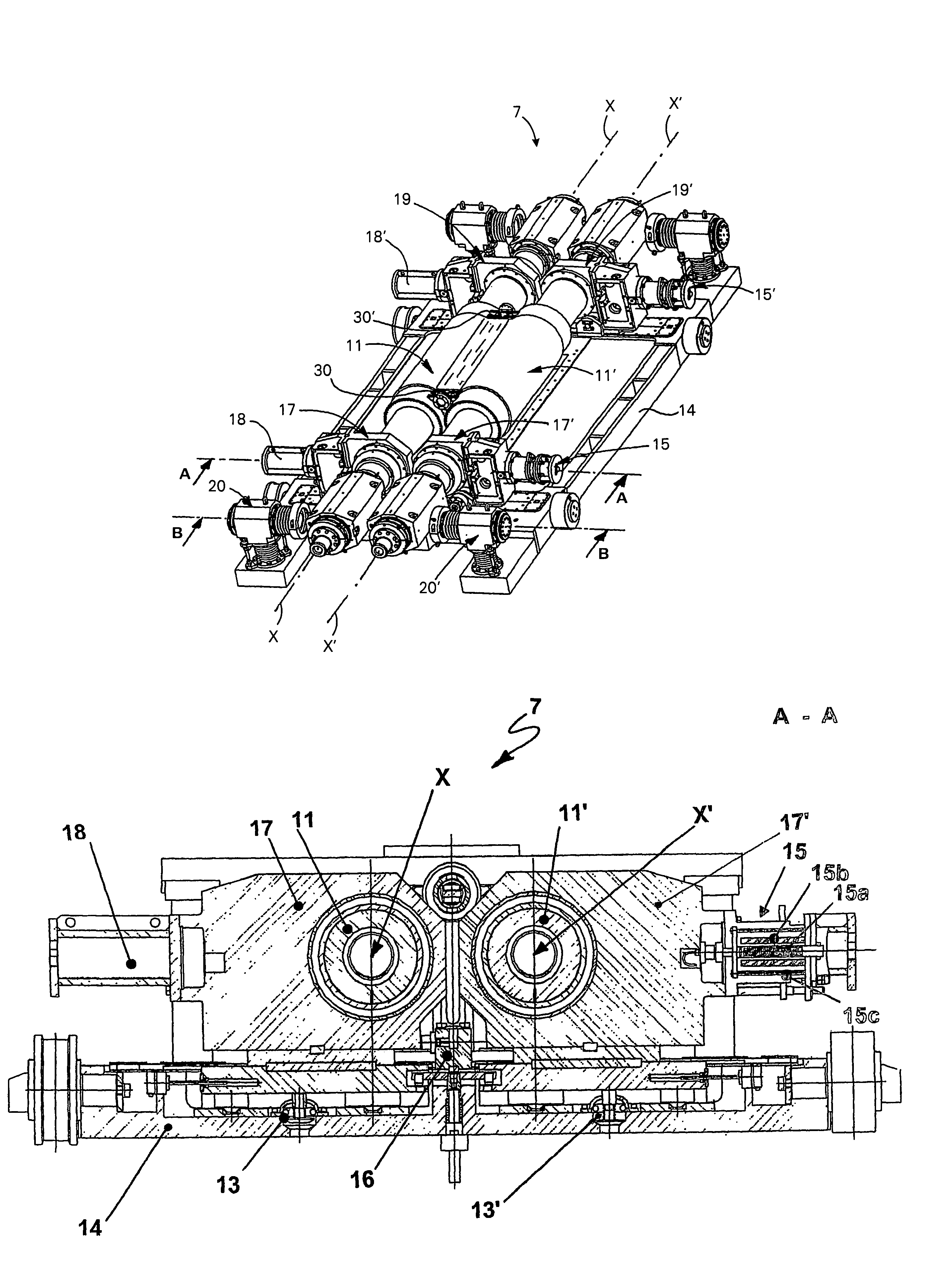
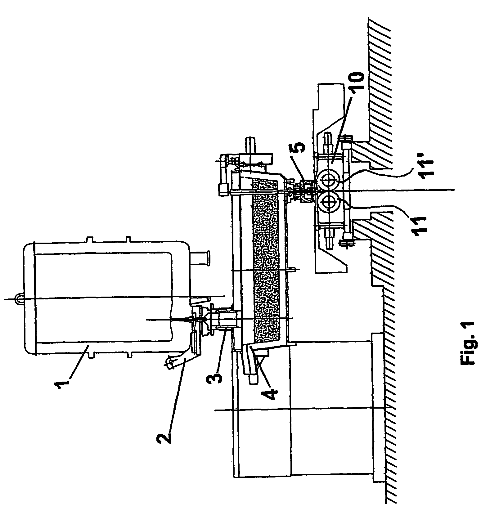
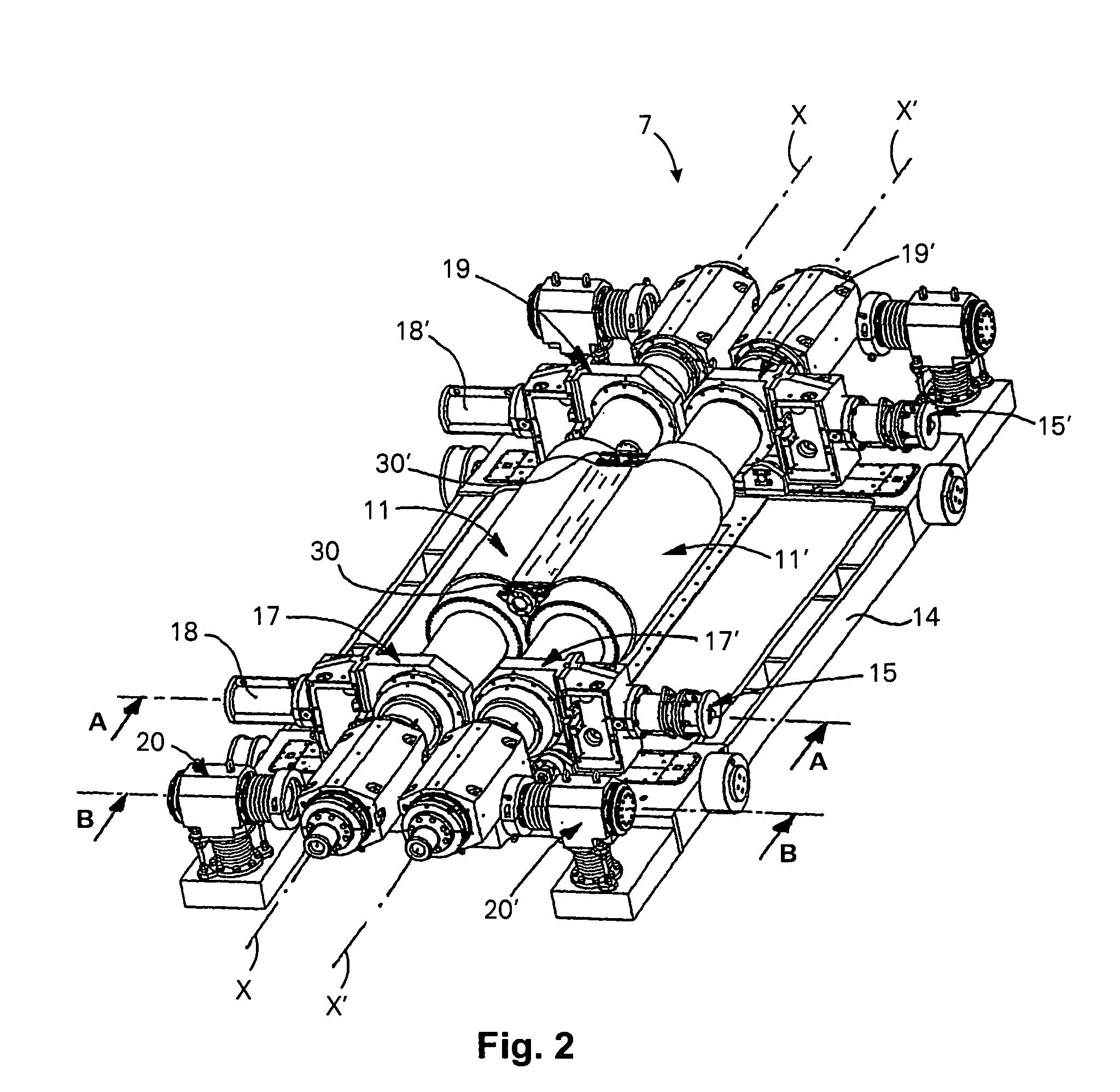
[0028]With reference to the above-mentioned Figures, the continuous casting device provides for a ladle 1 which unloads the liquid steel load through an unloading slide valve 2 and a conduit 3 into a tundish 4. From the latter, the steel passes through a further conduit 5 into an optional under-tundish, not shown, or through an unloading device into an ingot mould 10 comprised of a pair of counter-rotating cooled casting rolls 11, 11′, turning around their respective and mutually parallel axes X, X′. Two bulkheads indicated by the reference numeral 30 in FIG. 2 are provided to complete the ingot mould 10 and restrict the liquid metal in the direction of the roll axes between the rolls themselves by suitable means which thrust them against the roll end surfaces.

[0029]In such ingot mould 10, the liquid metal solidifies in contact with said rolls 11, 11′ and is extracted from the ingot mould in the form of a strip at high temperature, said strip following, below said ingot mould, by gr...


PUM

PropertyMeasurementUnit
thicknessaaaaaaaaaa
thicknessaaaaaaaaaa
thicknessaaaaaaaaaa

Abstract

Support device for an assembly (14) of the casting rolls (11, 11′) of a continuous metallic strip casting line comprising a movable support at each axial end. Such supports (17, 17′, 19, 19′) are provided with a hydraulic bearing (13) to reduce friction during motion with respect to the assembly. Between the movable supports of one of the rolls (11) and the assembly is located a hydraulic actuator (18), which thrusts the first roll (11′) towards the second roll (11′) against a stop (16). Between the second roll (11′) and the assembly there are located magnetostrictive actuators which thrust the second roll (11′) against the first roll (11). The device has a joint provided with a housing (22) inside which a telescopic tube (21) for the supply of the cooling water to conduits present in the rolls may slide. The housing (22) is connected to the assembly (14) by means of a bellows (27) allowing for oscillation.

Description

FIELD OF THE INVENTION[0001]This invention relates to a support device of ingot mould rolls for continuous metallic strip casting, and particularly to a friction-reducing device for the rolls during their adjusting movement. It also relates to a method for controlling the distance between the rolls constituting an ingot mould.STATE OF THE ART[0002]Metallic strips are normally produced starting from continuously cast ingots or slabs, which are reduced in thickness by a series of subsequent operations comprising the preforging, hot and cold lamination, together with other intermediate treatments, for example heat treatments.[0003]These operating methods involve very expensive plants and notable expenditure of energy.[0004]Hence, for some time the tendency is that of reducing the plant and business costs by casting products with thickness as close as possible to that of the final product; consequently, following the introduction of continuous slab casting, the thickness of the latter i...

Claims


Application Information

Patent Timeline
Patent Type & Authority Patents(United States)
IPC IPC(8): B22D11/06
CPCB22D11/0622B22D11/0682B22D11/0651
Inventor BOTHAM, BRIAN W.DE LUCA, ANDREAPOLONI, ALFREDOFAGGIANI, EDIKAPAJ, NUREDIN
Owner DANIELI & C OFF MEC SPA
Why Eureka
Try Eureka