
On-Board Centralized System For Regulating The Pressure Of The Tyres Of A Motor-Vehicle

a centralized system and tyre technology, applied in the field of motor vehicles, can solve the problems of estimating based on the difference between the speed, being generally far from precise and even fallacious

Active Publication Date: 2018-12-06
CENT RICERCHE FIAT SCPA
View PDF0 Cites 4 Cited by
  • Summary
  • Abstract
  • Description
  • Claims
  • Application Information

AI Technical Summary

Benefits of technology

The present invention provides an on-board centralized system for regulating the pressure of the tyres of a motor-vehicle that can be installed without substantial modifications to the wheel installation and configuration. The system is sturdy, safe, and reliable, and ensures a minimum safety level of pressure in the inner chambers of the tyres of the motor-vehicle. The system allows for accurate control of the pressure of the tyres based on the vehicle's operating characteristics. The plenum of the wheel is a cavity formed in the front surface of the wheel and closed by a removable cover that remains unchanged during wheel installation and removal. The system is easy to install and remove, and ensures safety and reliability.

Problems solved by technology

Indirect TPM systems, in fact, provide an estimate based upon the difference between the speed of rotation of the different wheels and are generally far from precise and even fallacious in the case where all the tyres are deflated in the same way.
Direct TPM systems, on the other hand, require installation of pressure sensors directly within the inner chamber of the tyres in wireless communication with the control unit, with all the complications that this entails.

Method used


Image

  • On-Board Centralized System For Regulating The Pressure Of The Tyres Of A Motor-Vehicle
  • On-Board Centralized System For Regulating The Pressure Of The Tyres Of A Motor-Vehicle
  • On-Board Centralized System For Regulating The Pressure Of The Tyres Of A Motor-Vehicle

Examples


Embodiment Construction

[0032]Further characteristics and advantages of the invention will emerge from the ensuing description, with reference to the annexed drawings, which are provided purely by way of non-limiting example and in which:

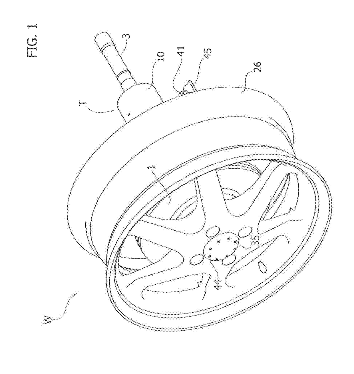
[0033]FIG. 1 is a perspective view of a driving wheel of a motor-vehicle with the system installed;

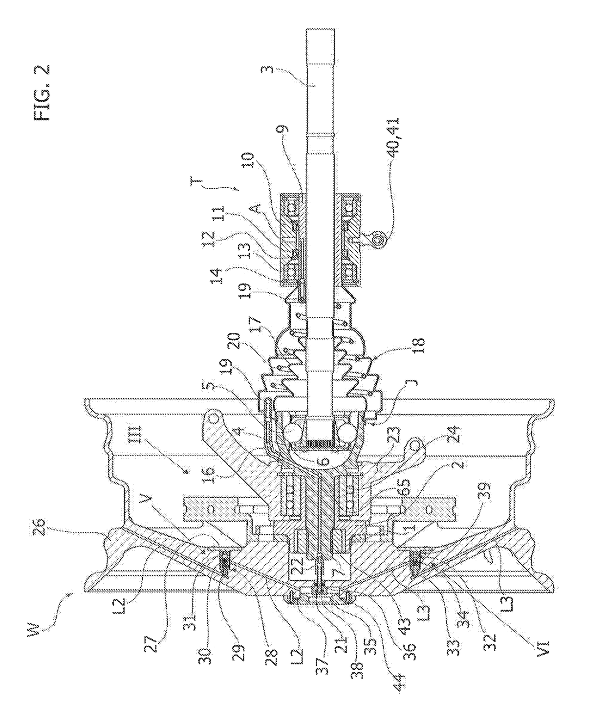
[0034]FIG. 2 is a cross-sectional view of the part of the system associated to the driving wheel, according to a preferred embodiment of the invention;

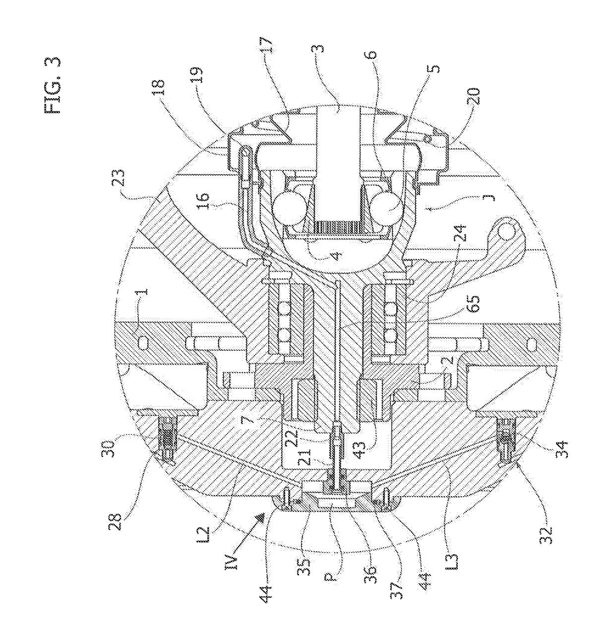
[0035]FIG. 3 is a view, at an enlarged scale, of the details denoted by the reference III in FIG. 2;

[0036]FIG. 4 is a view, at an enlarged scale, of the details denoted by the reference IV in FIG. 3;

[0037]FIGS. 5 and 6 are views, at an enlarged scale, of the details denoted by the references V and VI in FIG. 2;

[0038]FIGS. 7 and 8 are perspective views of some parts of the system illustrated in FIG. 2;

[0039]FIG. 9 is a front view of the details illustrated in FIG. 1;

[0040]FIG. 10 is a perspective view of a driving wheel of a mot...


PUM


Abstract

An on-board centralized system for regulating pressure of tyres of a vehicle includes a pressurized air source, two pneumatic rotary joints each associated to a driving wheel of the vehicle, and a circuit that sets in communication the pressurized air source with each rotary joint. An output member of a constant-velocity joint and a wheel spindle have an internal duct for air passage, connected to the respective rotary joint and to a plenum of the respective driving wheel. Each non-driving wheel has its wheel spindle traversed by an axial bore for air passage, connected to the circuit via a pneumatic rotary joint and a plenum of the non-driving wheel, which is connected to the inner chamber of the tyre. Each driving or non-driving wheel has its plenum connected to the inner chamber via two parallel lines, for deflating and inflating, respectively, the tyre interposed in which are respective one-way valves.

Description

FIELD OF THE INVENTION[0001]The present invention relates in general to motor-vehicles and in particular to an on-board centralized system for regulating the pressure of the tyres of a motor-vehicle having at least two, steering or non-steering, driving wheels and possibly two or more non-driving wheels, of the type referred to in the preamble of the annexed Claim 1. The invention may be used to particular advantage in passenger cars and light commercial vehicles.[0002]Centralized automatic systems for regulating the inflation pressure of the tyres of a motor-vehicle (the so-called Central Tyre-Inflation Systems—CTISs) have been known for some time. They are able to manage autonomously the pressure of tyres of a motor-vehicle through means for inflating and deflating tyres. The system is usually made up of valves and connections that enable a communication of air between the inner chamber of the tyre and a central part of the system that contains a source of positive pressure and po...

Claims


Application Information

Patent Timeline
Patent Type & Authority Applications(United States)
IPC IPC(8): B60C23/00
CPCB60C23/003B60C23/00318B60C23/00336B60C23/00345B60C23/00354B60C23/00363B60C23/0039
Inventor VITOLO, ROBERTOD'AMBROSIO, STEFANOSALAMONE, NICOLOMARTORANA, GIUSEPPEIELUZZI, MICHELEGABIATI, GIOVANNI LUIGISCANTAMBURLO, DARIO
Owner CENT RICERCHE FIAT SCPA
Learn More