Apparatus for fastening data storage device

a data storage device and apparatus technology, applied in the direction of electrical apparatus casings/cabinets/drawers, instruments, casings/cabinets/drawers, etc., can solve the problems of time-consuming and laborious disassembly and assembly process, and achieve the effect of reducing the use of extra tools, simplifying steps, and saving fixing tim

Active Publication Date: 2008-12-30
ASUSTEK COMPUTER INC
View PDF7 Cites 13 Cited by
  • Summary
  • Abstract
  • Description
  • Claims
  • Application Information

AI Technical Summary

Benefits of technology

[0006]An objective of the invention is to provide an apparatus for fastening a data storage device, and the apparatus for fastening a data storage device saves time for fixing the data storage device to a host, simplifies steps for disassembling and assembling, decreases usage of extra tools, avoids using screws, and accomplishes the fixing with simple configuration.
[0012]The leading unit on the bottom plate of the housing can guide the movement direction of the driving plate. Since the side edges or the connecting edge of the driving plate is adjacent to the protrudent piece of the lateral fastening plate, when the driving plate moves under the bottom plate along the leading unit, the side edges or the connecting edge of the driving plate can push the lateral fastening plate to cause the pull of the elastic member, so that the locating pins are moved into or out of the locating holes.
[0015]Furthermore, in one preferred embodiment of the invention, the side edges and the connecting edge of the driving plate can be preferred to be linear edges for smoothly pushing the driving plate.
[0017]In one preferred embodiment of the invention, the lateral fastening plate selectively includes at least a guiding pin which is protrudently formed on the lateral fastening plate, and the sidewalls of the housing include at least a guiding hole corresponding to the guiding pin. When the lateral fastening plate cooperates with the sidewalls of the housing, the guiding pin cooperates with the guiding hole of the sidewalls; when the driving plate is moved and pushes the lateral fastening plate, the guiding pin is moved along the guiding hole of the sidewalls to guide the movement direction of the lateral fastening plate. There is no limitation about the shape of the guiding pin in the preferred embodiment of the invention, and the guiding pin is preferred to be cylindraceous or conical, which can make the guide more smoothly.
[0018]In the preferred embodiment of the invention, the sidewalls of the apparatus for fastening a data storage device selectively provide a fastening hook for cooperating with the lateral fastening plate, thereby the rotatory angle of the lateral fastening plates is restricted when the lateral fastening plate is pushed by the driving plate. In this way, the lateral fastening plate is not separated from the sidewalls of the housing when the pushing force of the driving plate is too great.
[0020]The apparatus for fastening a data storage device in the embodiments of the invention does not need screws for fastening, and this saves time for fixing the data storage device to a host, simplifies steps for disassembling and assembling apparatuses for fastening, decreases usage of extra tools, and accomplishes the fixing with simple configuration. The apparatuses for fastening a data storage device in the embodiments of the invention apply to any computer which needs an apparatus for fastening a data storage device, and they have more advancement than those in conventional technology.

Problems solved by technology

However, by this fastening method, tools should be used to lock or remove screws for assembling or disassembling the data storage devices, so that the assembling or disassembling process is time-consuming and laborious.

Method used


Image

  • Apparatus for fastening data storage device
  • Apparatus for fastening data storage device
  • Apparatus for fastening data storage device

Examples


embodiment 1

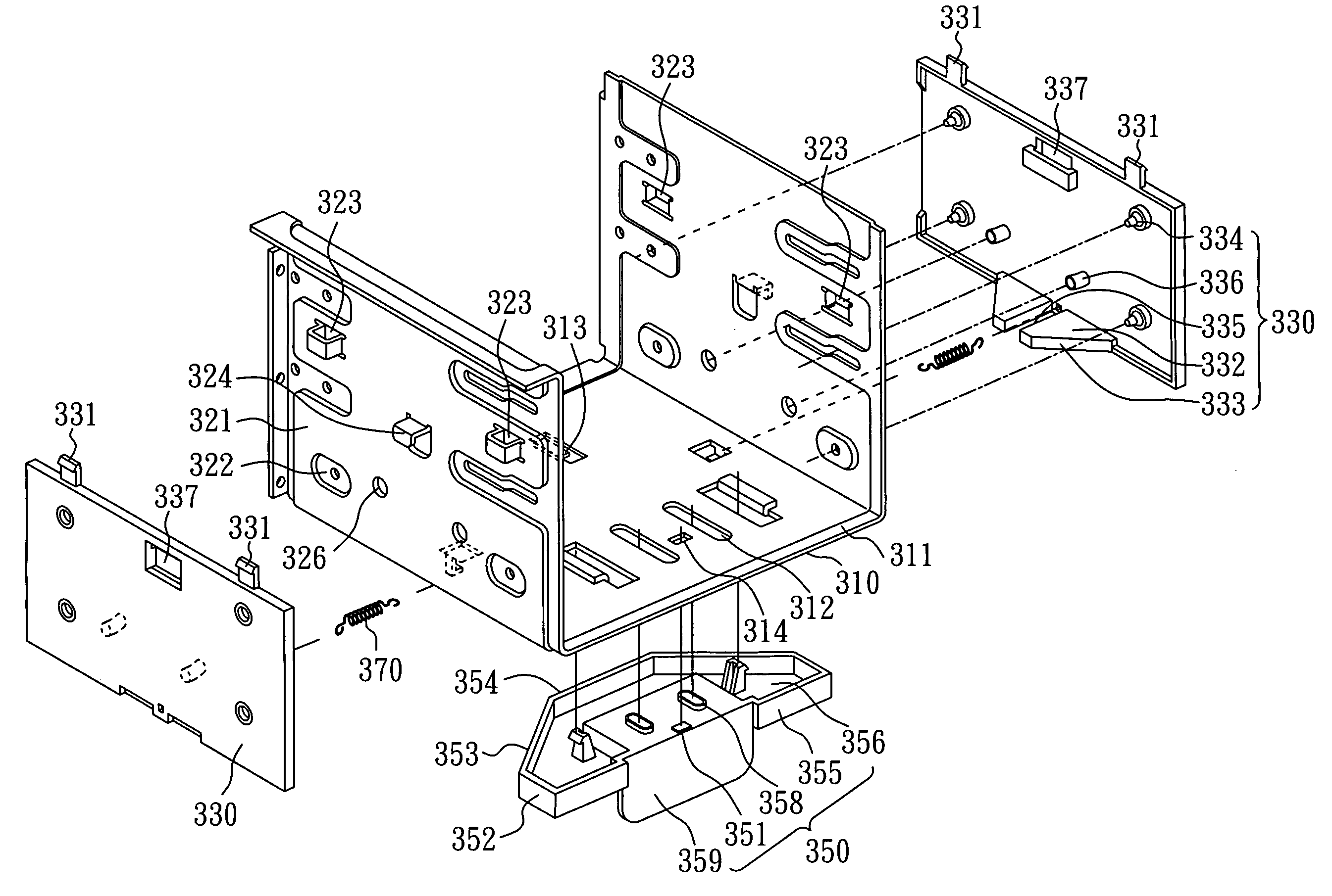
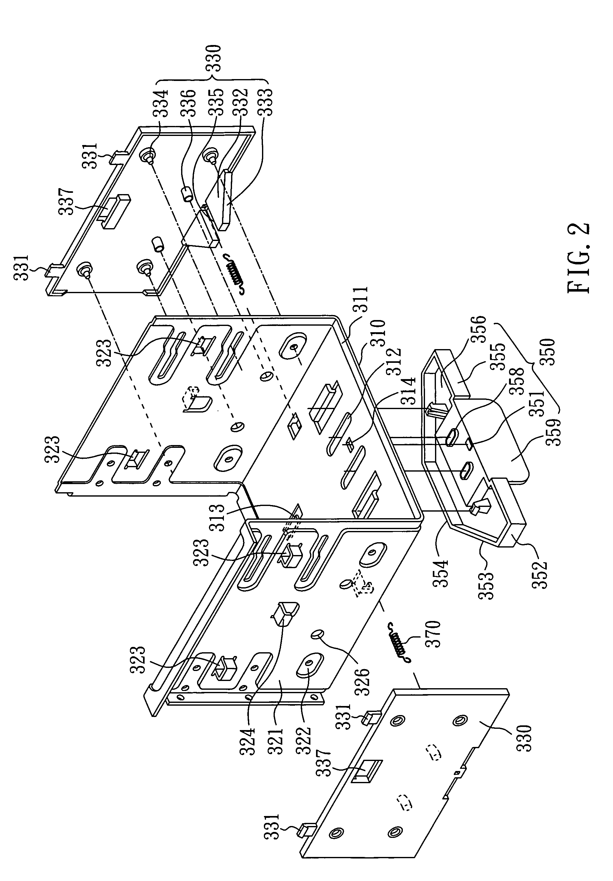
[0029]FIG. 2 is a diagram showing the disassembled components of the apparatus for fastening a data storage device of this embodiment.

[0030]The apparatus for fastening a data storage device of the embodiment applies to the housing of a computer host to fasten at least one data storage device or module which has a plurality of fixing holes.

[0031]In the present embodiment, elements of the apparatus for fastening a data storage device are shown in FIG. 2, and the elements include a housing 310, a driving plate 350, two lateral fastening plates 330, and two elastic members 370.

[0032]In the embodiment, the housing 310 includes a bottom plate 311 and two sidewalls 321, and the two sidewalls 321, which are symmetrically provided at two opposite sides of the bottom plate 311, are combined with the bottom plate 311 to form a space for holding one to three data storage devices or modules.

[0033]The bottom plate 311 has four leading grooves 312 as leading units, and the sidewalls 321 have a plu...

embodiment 2

[0053]As shown in FIG. 8, the apparatus for fastening a data storage device in the embodiment 2 is similar to that in the embodiment 1, except that a driving plate 850 includes only one connecting edge 853 which is adjacent to the trapezoid-shaped protrudent piece 332 of a lateral fastening plate 330, and only one lateral fastening plate 330 is provided. Other elements and actions of the elements are similar to those of the apparatus for fastening a data storage device in the embodiment 1, but the apparatus for fastening a data storage device in the embodiment 2 only uses locating pins 334 on one lateral fastening plate 330 for fastening. The apparatus for fastening a data storage device in the embodiment applies to the data storage device with lower stability requirement.


PUM


Abstract

The invention relates to an apparatus for fastening a data storage device, which is used to fasten a data storage device or module with a plurality of fixing holes. The apparatus for fastening a data storage device of the invention includes a housing, a driving plate, at least one lateral fastening plate, and an elastic member. As the driving plate moves, the lateral fastening plate is pushed to move laterally, whereby the locating pins move into or out of the locating holes on the sidewalls of housing to remove or fasten the data storage device. The data storage device can be fastened to a housing of a computer without screws, and a user can operate more conveniently.

Description

BACKGROUND OF THE INVENTION[0001]1. Field of the Invention[0002]The invention relates to an apparatus for fastening a data storage device and, more particularly, to an apparatus for fastening the data storage device of a computer.[0003]2. Description of the Related Art[0004]At present, a computer mostly consists of a host cooperated with data storage devices, such as a hard disk drive, an optical disk drive, a floppy disk drive or a card reader module, etc. The present method for fastening those data storage devices into the predetermined housing of the host always utilizes screws. The conventional fastening method, as shown in FIG. 1, is placing those data storage devices 103 into the interior housing 104 of the housing 101 of a host 100, and fastening the data storage devices 103 to the housing 100 by four to six screws 102 which pass through screw holes 105 in the housing 104 and fixing holes 106 in the data storage devices 103.[0005]However, by this fastening method, tools shoul...

Claims


Application Information

Patent Timeline
Patent Type & Authority Patents(United States)
IPC IPC(8): G06F1/16
CPCG11B33/124
Inventor HE, CHUN-MIN
Owner ASUSTEK COMPUTER INC
Why Eureka
Try Eureka