Method and device for compensating variations in fuel composition in a gas turbine system

a gas turbine and fuel composition technology, applied in the direction of engines, machines/engines, mechanical equipment, etc., can solve the problems of system efficiency and heat release quantity variations, and achieve the effect of increasing emissions or combustion fluctuations

Active Publication Date: 2009-01-06
SIEMENS ENERGY GLOBAL GMBH & CO KG
View PDF16 Cites 19 Cited by
  • Summary
  • Abstract
  • Description
  • Claims
  • Application Information

AI Technical Summary

Benefits of technology

[0008]It is therefore the object of this invention to make available a method for compensating variations in the fuel composition in a gas turbine system, a control device for adjusting the supply of fuel to a gas turbine system as well as a gas turbine system, in which increased emissions or combustion fluctuations when compensating the variations in the fuel composition can be avoided more effectively.
[0012]As mentioned above, it is clear that the compensation of variations in the fuel composition by adjusting the supply of fuel to the main burner stage by means of a regulator, which determines the fuel quantity, in the worst-case scenario, leads to an increase in emissions or to combustion fluctuations. The cause of this is that the fuel split is changed when adjusting the supply of fuel to the main burner stage. For instance, changing the fuel split between a pilot burner stage and a main burner stage can adversely affect the stability of the main burner flame, which is usually the flame of a lean air-fuel mixture. The lean air-fuel mixture, within the framework of the so-called dry denitrogenation serves to keep the emission values of the system low. In this way, a low stability of the flame of the lean air-fuel mixture has an adverse effect on the emission values of the system. By keeping the fuel split constant at a target value or adjusting the fuel split to a suitable new target value, on the other hand, the adverse effects on the stability of the main burner flame can be avoided or at least reduced so that the above-mentioned disadvantages can be avoided or reduced.
[0015]However, knowledge of the actual Wobbe index also allows the adaptation of the fuel split to a new, adapted target value or the keeping constant of the fuel split at the current target value, while the actual Wobbe index of the fuel is taken as the basis for the characteristic values of the regulator for adjusting the drop in pressure in the control valves of the individual burner stages.
[0026]In an advantageous embodiment of the gas turbine system according to the invention, said system comprises a fuel line, through which a fuel flow passes and a branching point on the fuel line for branching off a part of the fuel and for introducing the branched off fuel as an analysis sample flow into a branch line, which feeds the analysis sample flow to the analyzer. In this case, the branching point is arranged in such a way that the time, which is required by the fuel flow in order to cover the path from the branching point up to the fuel control valves, is long enough, so that the analysis sample flow can cover the stretch of way up to the analyzer, and the analyzer can analyze the fuel composition, the computing unit can calculate the Wobbe index, the updating unit can update the characteristic values of the regulator and the control device can adjust the fuel control valves before the fuel flow reaches the fuel control valves.

Problems solved by technology

However, variations in the fuel quality lead to variations in the released quantity of heat and thereby in the efficiency of the system.

Method used


Image

  • Method and device for compensating variations in fuel composition in a gas turbine system
  • Method and device for compensating variations in fuel composition in a gas turbine system

Examples


Embodiment Construction

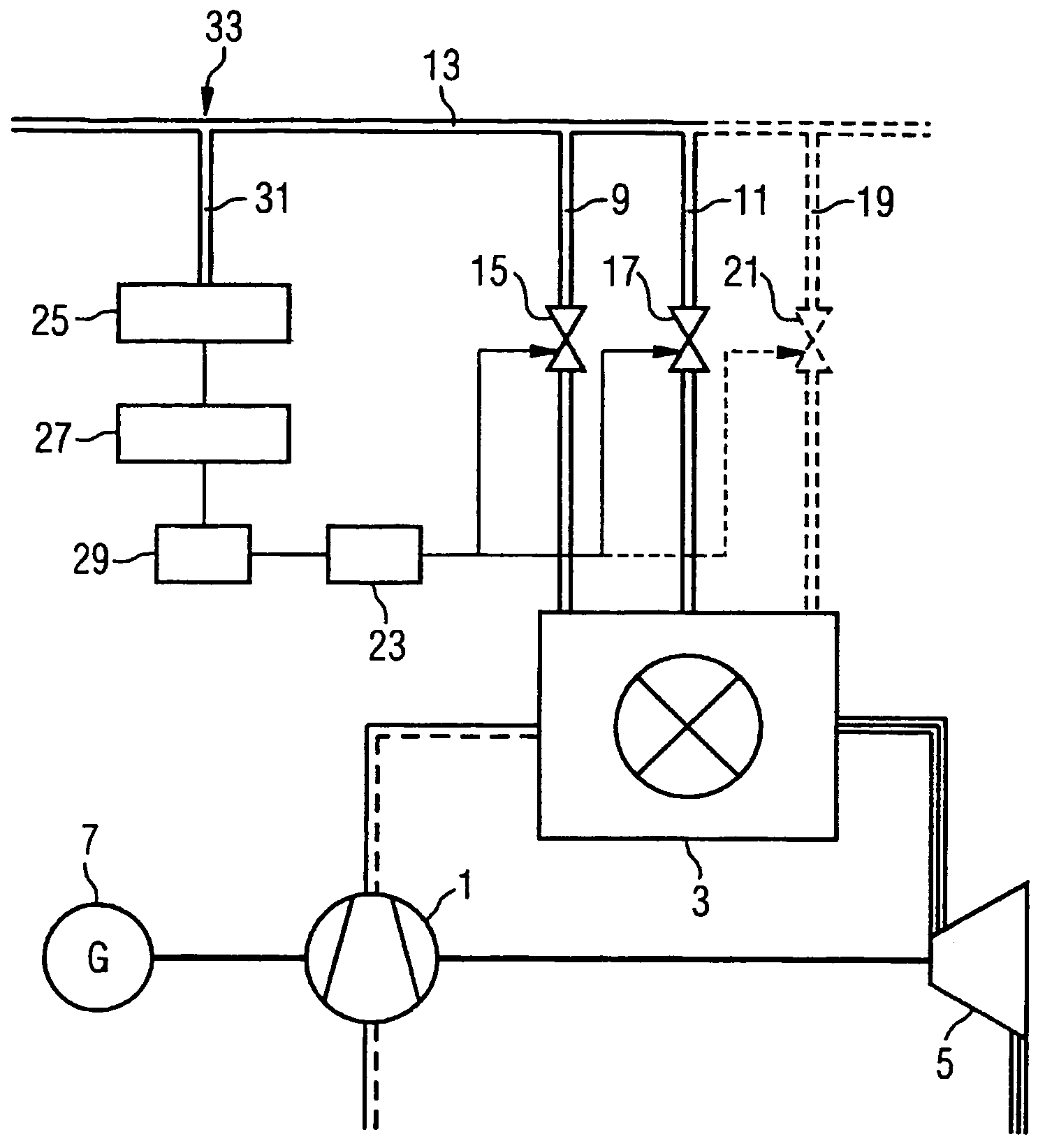
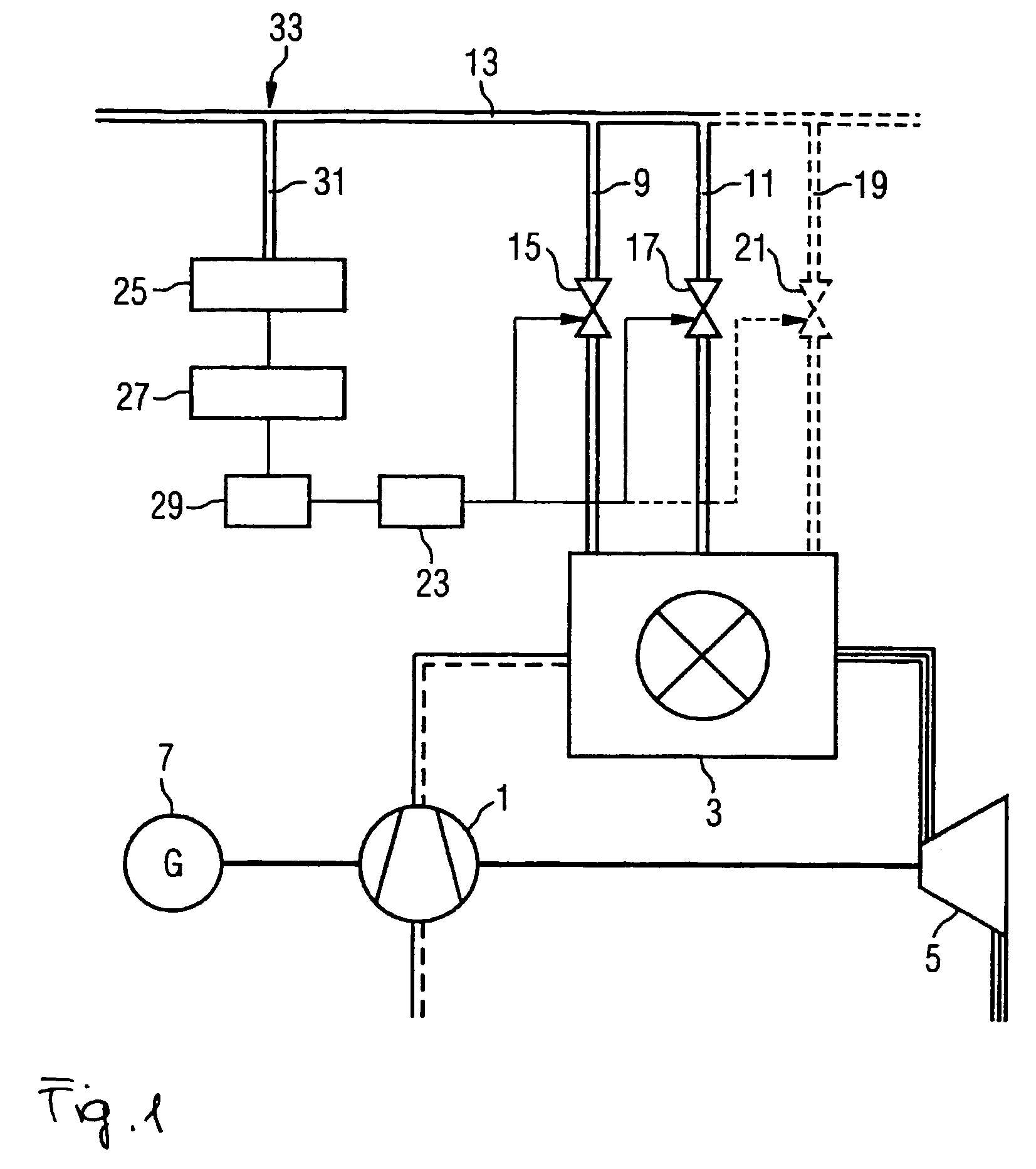
[0030]FIG. 1, which comprises a schematic diagram for a circuit to update the characteristic values of the regulator, shows a gas turbine system with a compressor 1, a combustion chamber 3 and a turbine 5, which is connected to a generator 7.

[0031]A first fuel feed line 9 and a second fuel feed line 11 lead to the combustion chamber 3, said lines branching off from a fuel line 13 and are in each case equipped with a fuel control valve 15, 17. By means of the fuel feed lines 9, 11, a pilot burner and a main burner (both not shown) are supplied with fuel. In addition to the pilot burner and the main burner, which are usually to be operated in parallel, in particular additional burner stages to be operated in parallel can be available, as is shown in the drawing by means of an additional fuel feed line 19 and an additional fuel control valve 21.

[0032]In order to be able to compensate for variations in the fuel composition, the gas turbine system shown in the Figure also comprises a reg...


PUM


Abstract

The invention relates to a method for compensating variations in fuel composition in a gas turbine system consisting of at least two parallel-operated burner stages, wherein the fuel supply to at least two of the burner stages is adjusted in response to variations in fuel composition, wherein the fuel split between the burner stages, i.e. the relative increase in speed of the fuel supplied to the burner stages, is adjusted to a target value or maintained at a target value during adjustment of the fuel supply. The target value can, for example be a constant or a function of one or several variables. More particularly, the gas turbine system can comprise a pilot burner stage and a main burner stage. When the fuel supply is adjusted, the fuel split between the pilot burner stage and the main burner stage is adjusted to a target value or maintained at a target value.

Description

CROSS REFERENCE TO RELATED APPLICATIONS[0001]This application is the US National Stage of International Application No. PCT / EP2004 / 011382, filed Oct. 11, 2004 and claims the benefit thereof. The International Application claims the benefits of European application No. EP03023212.8 filed Oct. 13, 2003, both applications are incorporated by reference herein in their entirety.FIELD OF THE INVENTION[0002]The invention relates to a method for compensating variations in the fuel composition in a gas turbine system, particularly in a gas turbine system consisting of at least two burner stages to be operated in parallel, and more particularly in a gas turbine system consisting of a pilot burner stage and a main burner stage.BACKGROUND OF THE INVENTION[0003]A gas turbine system includes in the simplest case, a compressor, a combustion chamber as well as a turbine. In the compressor, a compression of sucked-in air takes place, to which a fuel is subsequently added. In the combustion chamber, ...

Claims


Application Information

Patent Timeline
Patent Type & Authority Patents(United States)
IPC IPC(8): F02C9/26F02C9/34
CPCF02C9/34F05D2270/081F05D2270/08F02C9/26
Inventor BERENBRINK, PETERBLOMEYER, MALTE
Owner SIEMENS ENERGY GLOBAL GMBH & CO KG
Why Eureka
Try Eureka